
Feeding device of automatic patch pocket machine

A bag sticking machine and material cutting technology, which is applied in the direction of cloth feeding mechanism, sewing machine components, textiles and paper making, etc., can solve the problems of rising manufacturing cost, large space occupation, and inability to get rid of it, so as to achieve agile cutting action and manufacturing. Low cost and reasonable layout

Inactive Publication Date: 2012-11-28
杭州贵衣自动化设备有限公司
View PDF0 Cites 0 Cited by
  • Summary
  • Abstract
  • Description
  • Claims
  • Application Information

AI Technical Summary

Problems solved by technology

The floor-type blanking device is equipped with a heavy bottom plate on the ground below the sewing area of ​​the machine head, a column is set in the middle, and a blanking plate is arranged horizontally on the bottom plate on the ground. The blanking plate is equipped with two sets of bearing seats. , There are two right-angled elbows between the two bearing seats of each group of bearing seats, one right-angled elbow is the pressing pipe, and the other right-angled elbow is the pressing pipe, and the pressing pipe is more than the pressing pipe. Pipe height, the root of the right-angled elbow has a pin positioned in the shaft hole of the bearing seat, a hoop is arranged in the middle of the right-angled elbow, and the root of the cylinder connected to the piston head of the cylinder is provided with a cylinder seat. A pin is connected to the tail of the cylinder, and the cylinder and the right-angle elbow are installed at an inclination. The swing of the right-angle elbow is realized through the telescopic movement of the cylinder piston rod. At this time, the sewing upper pressing plate is lifted, and the material-pushing cylinder moves the upper part of the fabric to the blanking plate to complete the blanking. The disadvantage of this floor-type blanking device is that it takes up a lot of space, and the mechanism is not installed with the main machine. In addition, due to The unloading device can only be set under the front of the sewing area, hindering the normal work of the operator
The random unloading device is installed on the lower bracket of the bed body and does not fall to the ground. Its working principle is similar to that of the floor-type unloading device. It includes a pressing elbow and a feeding elbow, and the swing of the elbow is driven by a rotary cylinder. At the same time, the pressing rod is also responsible for the function of receiving materials. When working, the pressing rod swings backward to make the cloth lean against a baffle of the machine tool, and the material elbow swings forward to carry the cloth on the pressing rod. This random type The defect of the unloading device is similar to that of the floor-type unloading device. The working area cannot get rid of the sewing area, which hinders the normal work of the operator. In order to overcome this defect, a few manufacturers have set up a set of accompanying vehicles on the random unloading device. That is, the fabric is dragged out of the sewing area to the right by the accompanying trolley and then unloaded, but this will greatly increase the manufacturing cost

Method used


Image

  • Feeding device of automatic patch pocket machine
  • Feeding device of automatic patch pocket machine
  • Feeding device of automatic patch pocket machine

Examples


Embodiment Construction

[0012] A preferred embodiment will be given below, and the present invention will be described more clearly and completely in conjunction with the accompanying drawings.

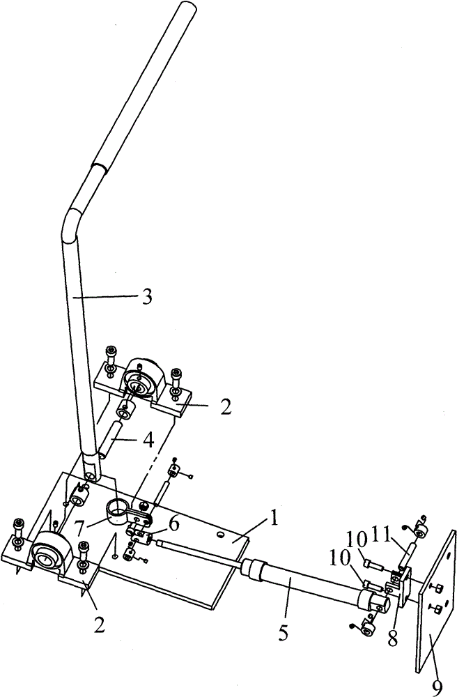
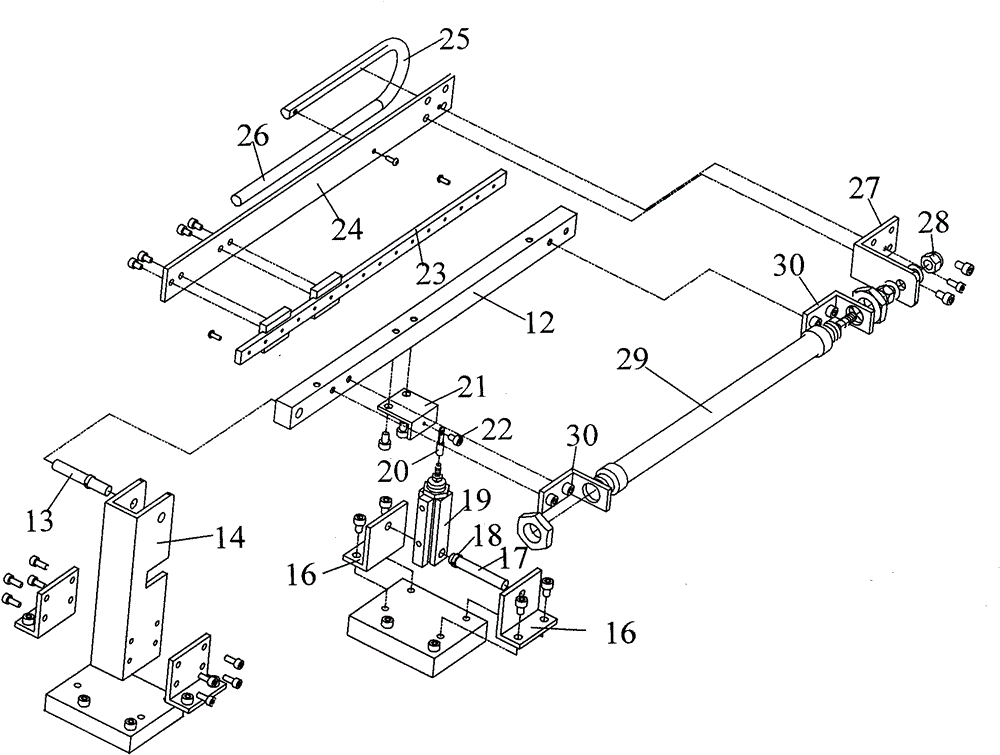
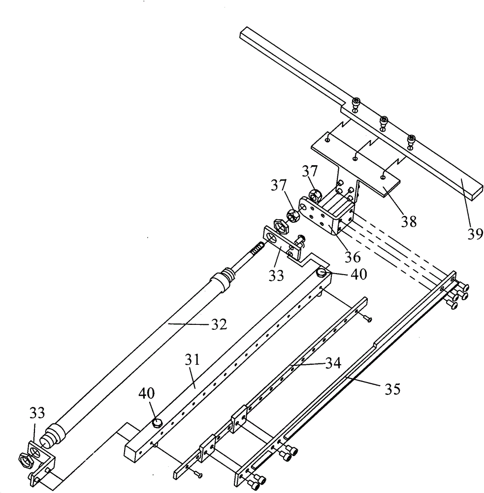
[0013] The unloading device of the automatic bag pasting machine of the present invention comprises a material pressing and receiving mechanism located under the right side of the bag pasting machine body, a material dragging mechanism located above the right side of the bag pasting machine table top, and a material dragging mechanism located on the right side of the bag pasting machine table top. The push mechanism below.

[0014] Such as figure 1 As shown, the pressing and receiving mechanism of the present invention is provided with a horizontal mounting plate 1 on the frame of the bag pasting machine, and two bearing blocks 2 are arranged on the horizontal mounting plate 1, and the bearing blocks 2 are fixed with the horizontal mounting plate 1 by screws. A right-angled elbow 3 is sandwiched between the...


PUM


Abstract

The invention discloses a feeding device of an automatic patch pocket machine. The feeding device comprises a material pressing and receiving mechanism, a material dragging mechanism and a material pushing mechanism, wherein the material pressing and receiving mechanism comprises elements such as a horizontal installation plate and the like; bearing seats and the horizontal installation plate arefixed; a right-angled bent pipe is positioned between the two bearing seats; a first cylinder seat is fixed on a vertical installation plate; the material dragging mechanism comprises elements such as a transverse beam and the like; a second cylinder seat is connected with a second cylinder; the second cylinder is connected with the transverse beam through a connecting plate and an axial screw; annular round steel is arranged at the front end of a first aluminum dummy spindle; a first connecting frame is positioned at one side of the first aluminum dummy spindle; a third cylinder is connectedwith the transverse beam through a third cylinder seat; the material pushing mechanism comprises elements such as a longitudinal beam and the like; a fourth cylinder is positioned at one side of the longitudinal beam, is fixed on a fourth cylinder seat and is fixed together with a second connecting frame; a right-angled plate frame is arranged in the middle of the second connecting frame; and a transverse material pushing rod is fixed above the right-angled plate frame. The feeding device of the automatic patch pocket machine has a simple structure and low manufacturing cost.

Description

technical field [0001] The invention relates to an automatic bag sticking machine, in particular to a material unloading device of the automatic bag sticking machine. Background technique [0002] The automatic bagging machine generally includes automatic procedures such as non-ironing hemming, feeding sewing and blanking, and the blanking procedure is the last process. Common unloading devices for automatic bagging machines include floor-type unloading devices and random unloading devices. The floor-type blanking device is equipped with a heavy bottom plate on the ground below the sewing area of ​​the machine head, a column is set in the middle, and a blanking plate is arranged horizontally on the bottom plate on the ground. The blanking plate is equipped with two sets of bearing seats. , There are two right-angled elbows between the two bearing seats of each group of bearing seats, one right-angled elbow is the pressing pipe, and the other right-angled elbow is the pressi...

Claims


Application Information

Patent Timeline
Patent Type & Authority Patents(China)
IPC IPC(8): D05B35/00
Inventor 黄志云
Owner 杭州贵衣自动化设备有限公司
Learn More