Layered runner motor shell of dust collector

A vacuuming motor and stratified flow technology, applied in the direction of vacuum cleaners, casings/covers/supports, electrical components, etc., which can solve the problems of insignificant noise reduction effect and short gas flow passages.

Inactive Publication Date: 2011-08-03
LG ELECTRONICS (TIANJIN) APPLIANCES CO LTD
View PDF1 Cites 10 Cited by
  • Summary
  • Abstract
  • Description
  • Claims
  • Application Information

AI Technical Summary

Problems solved by technology

[0010] The present invention aims to solve the ubiquitous problems in the prior art that the gas flow path in the motor casing is too short, and the noise reduction effect is not obvious by simply using foam plastics to absorb sound, and provides a layered double-flow path motor casing for a vacuum cleaner.

Method used


Image

  • Layered runner motor shell of dust collector
  • Layered runner motor shell of dust collector
  • Layered runner motor shell of dust collector

Examples


Embodiment Construction

[0033] The present invention will be described in detail below in conjunction with the accompanying drawings and embodiments.

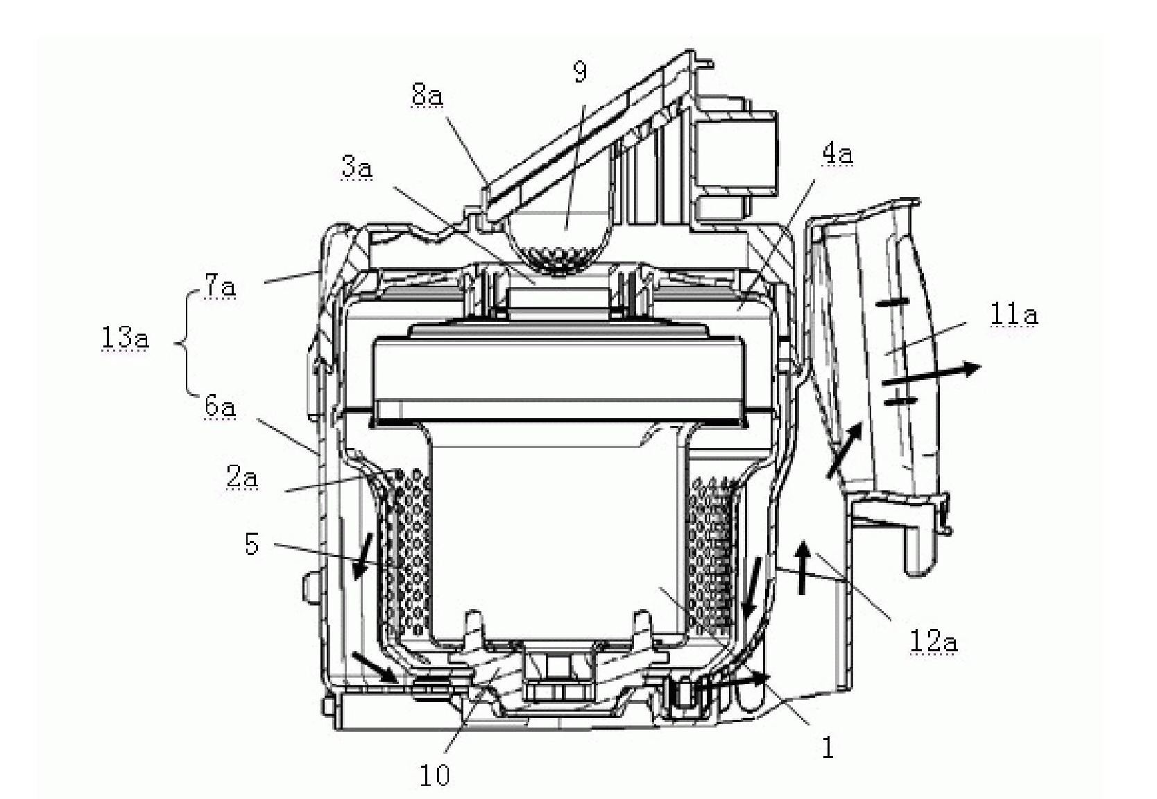
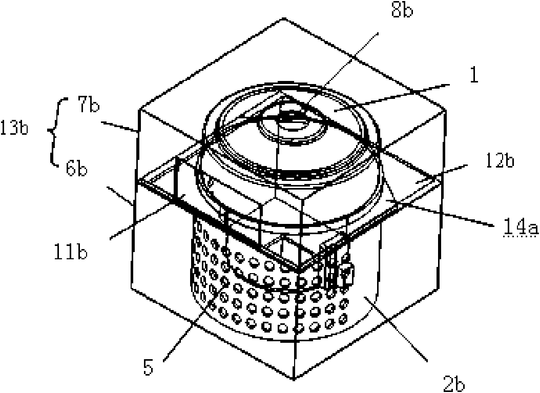
[0034] A layered channel motor casing of a vacuum cleaner, comprising an inner casing 2b. , 13c, the housing 13b, 13c is composed of the housing body 6b, 6c and the housing cover 7b, 7c, the housing air inlet 8b, 8c formed on the top of the housing cover 7b, 7c, and the exhaust port for discharging gas from the housing 13b, 13c 11b, 11c, and in the outer shell 13b, 13c are formed the diaphragm 14a, 14b that partly separates the inner space, and the vent hole 5 is formed in the diaphragm 14a, 14a on the side of the center line of the inner casing 2b, 2c. 14b below the surrounding wall.

[0035] The horizontal partition 14a of the vacuum cleaner layered runner motor casing is formed on the outer peripheral wall of the front part of the inner casing 2b. Thereby, the passage on the upper layer of the partition and the passage on the lower layer of the p...


PUM


Abstract

The invention discloses a layered runner motor shell of a dust collector and belongs to electric mechanical equipment of the dust collector. The layered runner motor shell of the dust collector comprises inner shell bodies, square outer shells, outer shell air inlets and exhaust ports, wherein dust collection motors are respectively arranged in the inner shell bodies; the inner shell bodies are provided with vent holes; the square outer shells are arranged outside the inner shell bodies at certain spatial distance; each outer shell consists of an outer shell body and an outer shell cover; the outer shell air inlets are formed on the top of the corresponding outer shell covers; the exhaust ports are used for exhausting air from the outer shells; transverse clapboards for partly dividing the inside spaces of the outer shell are formed in the outer shells; the vent holes are formed on the peripheral walls of the inner shell bodies at the side that the center lines of the circle centers are passed through below the transverse clapboard so as to form lower clapboard channels and upper clapboard channels; and uplink runners and downlink runners are formed at the parts which are not divided by the transverse clapboards. By the layered runner motor shell adopting the design, the lengths of the runners for exhausting air are increased and the transmission loss of noise is improved, so that the noises generated when the motor shell of the dust collection exhausts the air are reduced.

Description

technical field [0001] The invention relates to electrical machinery equipment of a vacuum cleaner, in particular to a layered channel motor casing of the vacuum cleaner. Background technique [0002] Vacuum cleaner is a cleaning and sanitary electrical device used to remove dust from floors, carpets, walls, furniture, clothing and various gaps. [0003] According to the shape of the vacuum cleaner, it can be divided into vertical vacuum cleaners, horizontal (tank) vacuum cleaners and portable vacuum cleaners. [0004] The general structure of the vacuum cleaner includes a vacuum cleaner motor that generates suction by introducing current, a suction nozzle that forms an air path system, a dust suction hose, a filter device, and a dust collection device that collects inhaled matter. [0005] The vacuum cleaner motor, which is provided inside the vacuum cleaner body and generates negative pressure suction, is placed in the motor box and generates an air discharge airflow. ...

Claims


Application Information

Patent Timeline
IPC IPC(8): H02K5/24A47L9/00
Inventor 武甜甜杨柱
Owner LG ELECTRONICS (TIANJIN) APPLIANCES CO LTD
Why Eureka
Try Eureka