Motor casing with layered long flow channels

A technology of motor casing and flow channel, applied in the direction of casing/cover/support, electrical components, electromechanical devices, etc., can solve problems such as noise reduction of motor casings

Inactive Publication Date: 2015-06-10
LG ELECTRONICS (TIANJIN) APPLIANCES CO LTD
View PDF5 Cites 0 Cited by
  • Summary
  • Abstract
  • Description
  • Claims
  • Application Information

AI Technical Summary

Problems solved by technology

[0015] The present invention aims to solve the noise reduction problem of the motor casing in the prior art, and provides a layered long-channel motor casing

Method used


Image

  • Motor casing with layered long flow channels
  • Motor casing with layered long flow channels
  • Motor casing with layered long flow channels

Examples


Embodiment Construction

[0046] The present invention will be described in detail below in conjunction with the accompanying drawings and embodiments.

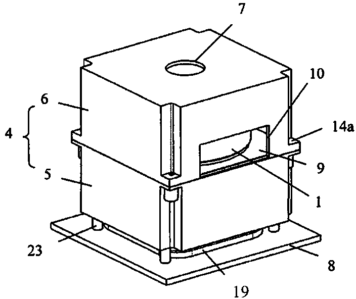
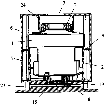
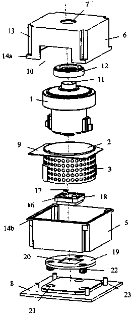
[0047] Figure 7 It is a schematic diagram of the longitudinal section structure of the present invention; Figure 8 It is a schematic diagram of the decomposition structure of the present invention; Figure 9 It is a schematic diagram of an exploded structure of another embodiment of the present invention.

[0048] Inside the body (not shown) of the horizontal vacuum cleaner, the dust collection motor 1 is installed in the inner shell 2, and uniformly distributed ventilation holes 3 are formed on the peripheral wall of the inner shell 2 on one side passing the center line of the circle center. The outside of the inner shell 2 is also provided with a square shell 4 keeping a certain space distance therefrom, and the shell 4 is formed by combining the outer shell 5 and the shell cover 6 . The four corners of the outer shell 5 and the outer shell 6 p...


PUM


Abstract

The invention discloses a motor casing with layered long flow channels, belonging to electrical mechanical equipment of a vacuum cleaner. The motor casing with layered long flow channels comprises a built-in vacuum motor, an inner casing with air holes, a square outer casing and an outer casing cover, wherein the inner casing is formed on one side; the square outer casing is arranged outside the inner casing and separated from the inner casing for a certain spatial distance; an air inlet is formed at the top of the outer casing cover and an air outlet is formed on one side of the outer casing cover; a lower-layer flow channel and an upper-layer flow channel are formed respectively in the outer casing and in the outer casing cover by a lateral partition; an up channel is formed on the lateral partition opposite to the air outlet in direction; an air inlet channel is formed between the air inlet of the outer casing and the air inlet of the motor; and a space dividing cover on which muffling holes are formed is arranged in the upper-layer flow channel on the periphery of the motor in the outer casing cover. Because the motor casing with layered long flow channels is designed such, based on the original double-layer motor casing with a long flow channel, the limited space in the upper-layer flow channel is fully used, and the space dividing cover with muffling holes is additionally arranged, thereby further increasing the length of the upper-layer flow channel and further reducing noise.

Description

technical field [0001] The invention relates to electrical mechanical equipment of a vacuum cleaner, in particular to a layered long-channel motor casing. Background technique [0002] Vacuum cleaner is a cleaning and sanitary electrical device used to remove dust from floors, carpets, walls, furniture, clothing and various gaps. [0003] According to the shape of the vacuum cleaner, it can be divided into vertical vacuum cleaners, horizontal (tank) vacuum cleaners and portable vacuum cleaners. [0004] The general structure of the vacuum cleaner includes a vacuum cleaner motor that generates suction by introducing current, a suction nozzle that forms an air path system, a dust suction hose, a filter separation device, and a dust collection device that collects inhaled matter. [0005] The vacuum cleaner motor, which is provided inside the vacuum cleaner body and generates negative pressure suction, is placed in the motor box and generates an air discharge airflow. [0006...

Claims


Application Information

Patent Timeline
Patent Type & Authority Patents(China)
IPC IPC(8): H02K5/24
Inventor 武甜甜肖宗亮
Owner LG ELECTRONICS (TIANJIN) APPLIANCES CO LTD
Why Eureka
Try Eureka