
Centrifugal fan impeller for range hood

A centrifugal fan and range hood technology, which is applied in the direction of machines/engines, mechanical equipment, liquid fuel engines, etc., can solve the problems of increased noise, decreased aerodynamic performance of the impeller, flow separation of the blade path, etc., and achieves low impact loss and reduced Swirl flow, effect of reducing air intake loss

Inactive Publication Date: 2011-08-03
MIDEA GRP CO LTD
View PDF5 Cites 4 Cited by
  • Summary
  • Abstract
  • Description
  • Claims
  • Application Information

AI Technical Summary

Problems solved by technology

At present, the range hoods on the market mostly use centrifugal fans, and the centrifugal impellers are mostly made of sheet metal materials, and the blades are mostly arc plate structures, such as the Chinese utility model patent "a fan impeller structure for deep range hoods" (patent No. ZL98225550.0) discloses a circular arc plate blade type centrifugal impeller. The circular arc plate blade type centrifugal impeller has a big disadvantage that the blade path is prone to flow separation, which leads to a decrease in the aerodynamic performance of the impeller and an increase in noise.

Method used


Image

  • Centrifugal fan impeller for range hood
  • Centrifugal fan impeller for range hood
  • Centrifugal fan impeller for range hood

Examples


Embodiment 1

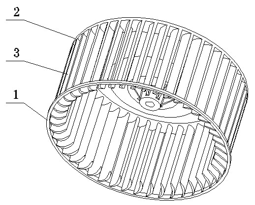
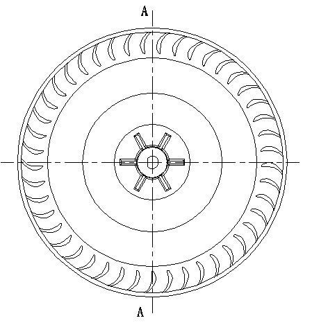
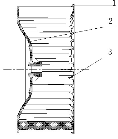
[0021] see Figure 1 to Figure 4 The centrifugal fan impeller of the range hood includes an end ring 1, a wheel disc 2 and a plurality of blades 3, the outer edge of one end of the blade 3 is connected with the inner edge of the end ring 1, and the other end is connected with the outer edge of the wheel 2. The edge parts are connected, and the three are connected into a whole to form a whole.

[0022] The cross-section of the above-mentioned blade 3 is an airfoil structure, and the method for generating the profile line of the airfoil structure adopts the method of superimposing the conventional symmetrical airfoil thickness on the mid-arc, such as Figure 4 shown.

[0023] like Figure 4 As shown, the middle arc BEF of the above-mentioned airfoil structure is composed of two tangent arcs BE and EF, and the tangent point E on it is the maximum camber position of the airfoil structure (that is, the middle arc of the airfoil is at the point E The tangent is parallel to the st...

Embodiment 2

[0030] see Figure 5 to Figure 7 , the impeller of the centrifugal fan of the range hood, its main difference from Example 1 is that the air intake mode of the impeller is double-sided air intake, both ends of the impeller are provided with end rings 1, and there are a number of The blades 3 are equal, and the blades 3 on both sides of the disc 2 are arranged in a staggered manner. Other undescribed parts are the same as in Example 1.

[0031] The actual test shows that, under the same conditions, the noise of the double-inlet impeller with staggered blades on both sides is reduced by about 1dB compared with the double-inlet impeller with aligned arrangement.


PUM


Abstract

The invention relates to a centrifugal impeller for a range hood. The centrifugal fan impeller comprises an end ring, a wheel disc and a plurality of blades; an outer edge part of one end of each blade is connected with an inner edge part of the end ring, and the other end face of each blade is connected with an outer edge part of the wheel disc; the centrifugal fan impeller is characterized in that: the cross section of each blade has an airfoil shape; a method for superposing the conventional symmetrical airfoil thickness on a central arched curve is adopted by a generation method for an airfoil molded line, and the central arched line of an airfoil consists of two sections of arcs BE and EF which are tangent to each other. A tangent point E of the arcs BE and EF is the maximum bending position of the airfoil. A projection point of E on a straight line BF where the chord length is is D point, the length of a segment BD is a, the length of the chord BF of the airfoil is c, the maximum bending of the airfoil structure is h, h / c is the maximum relative bending, the maximum thickness of the airfoil structure is L, and L / c is the maximum relative thickness of the airfoil structure. The centrifugal impeller can prevent flow separation in a blade channel or reduce the flow separation degree, the eddy current in the blade channel is reduced, flow loss in the blade channel is reduced, and the inlet loss and noise can be reduced.

Description

technical field [0001] The invention relates to a centrifugal fan impeller of a range hood. Background technique [0002] With the progress of society and the improvement of people's daily life, range hoods are widely used and spread to thousands of households. The fan is the heart and driving force of the range hood, and the impeller is the core component of the fan, and its performance directly affects the aerodynamic performance and noise of the range hood. At present, the range hoods on the market mostly use centrifugal fans, and the centrifugal impellers are mostly made of sheet metal materials, and the blades are mostly arc plate structures, such as the Chinese utility model patent "a fan impeller structure for deep range hoods" (patent No. ZL98225550.0) discloses a circular-arc-blade centrifugal impeller. The circular-arc-blade centrifugal impeller has a big disadvantage that the blade path is prone to flow separation, which leads to a decrease in the aerodynamic per...

Claims


Application Information

Patent Timeline
Patent Type & Authority Applications(China)
IPC IPC(8): F04D29/28
Inventor 梁之博丁蛟李志强季俊生黎本峰
Owner MIDEA GRP CO LTD
Learn More