
Farming machine capable of realizing laminated cutting

A tiller and crossbeam technology, applied in the field of multi-purpose layered cutting tiller, can solve the problems of unreachable, large resistance, low efficiency, etc.

Inactive Publication Date: 2011-08-03
乔生
View PDF0 Cites 1 Cited by
  • Summary
  • Abstract
  • Description
  • Claims
  • Application Information

AI Technical Summary

Problems solved by technology

[0003] The purpose of the present invention is to provide a layered cutting tillage machine to solve the problem of large resistance, low efficiency, high energy consumption, heavy pollution, and failure to achieve the ideal effects of subsoiling, crushing soil and weeding in the farming process of existing agricultural farming machines. And the phenomenon of serious pressing and burying of seedlings when going to the ground

Method used


Image

  • Farming machine capable of realizing laminated cutting
  • Farming machine capable of realizing laminated cutting
  • Farming machine capable of realizing laminated cutting

Examples


Embodiment Construction

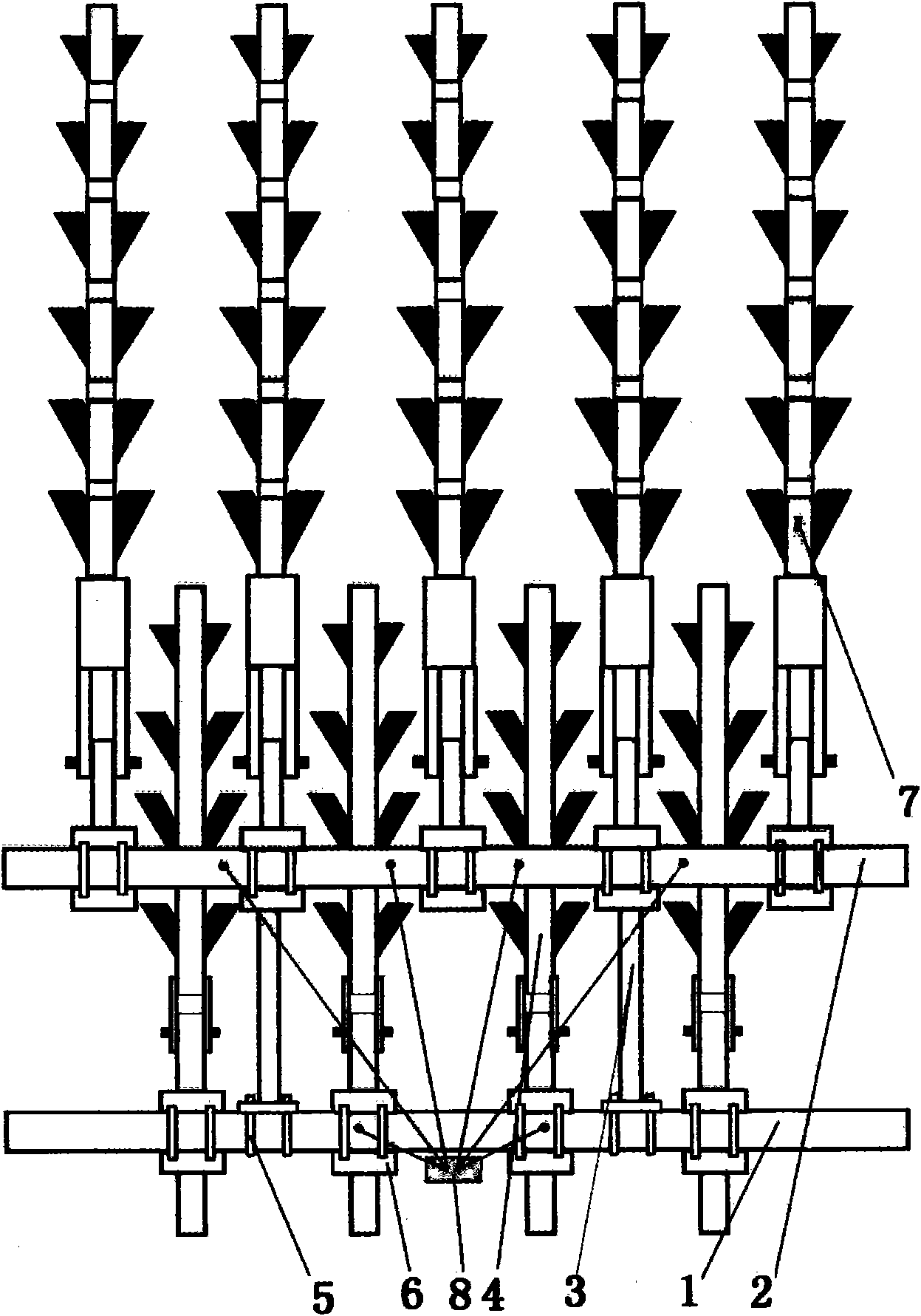
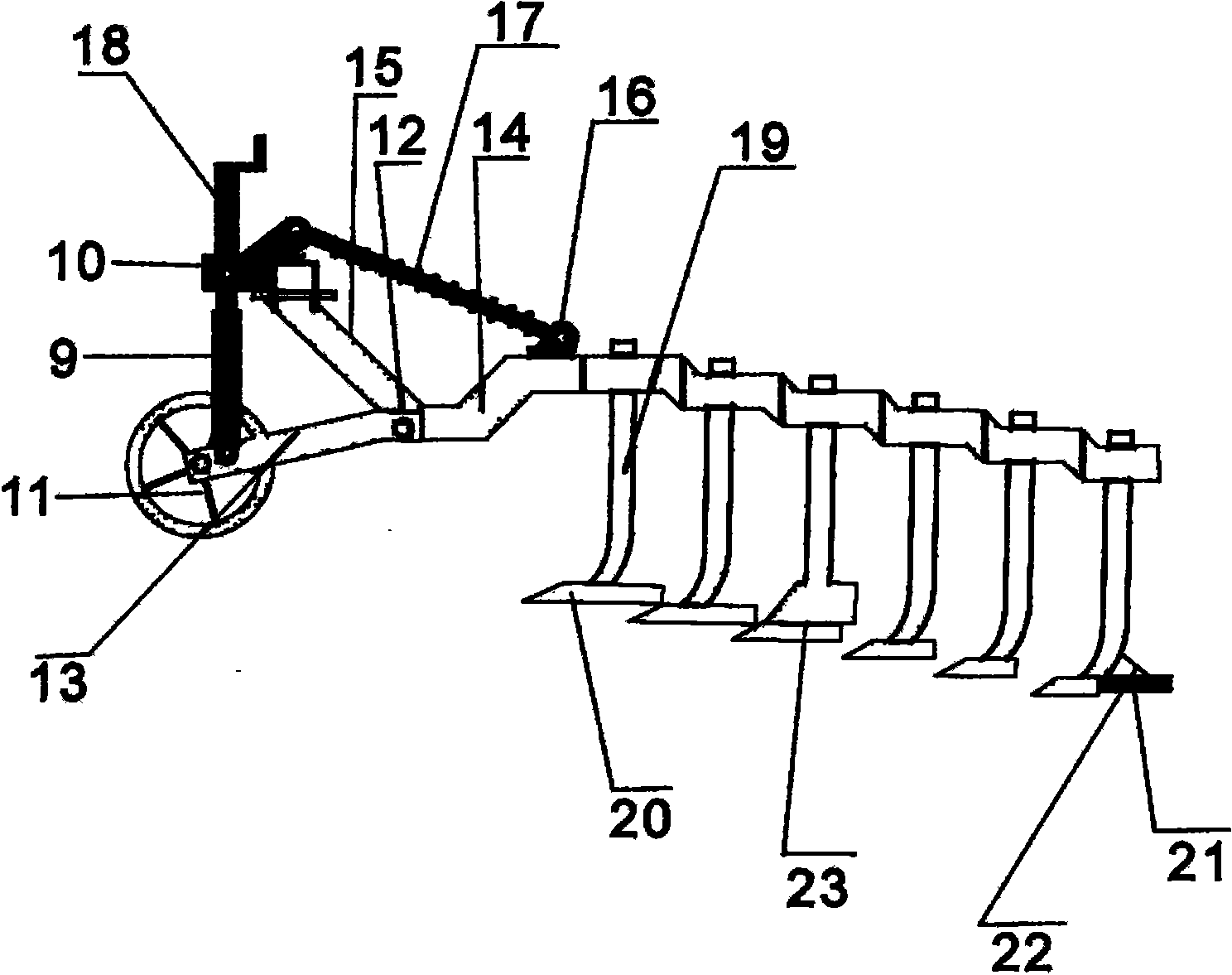
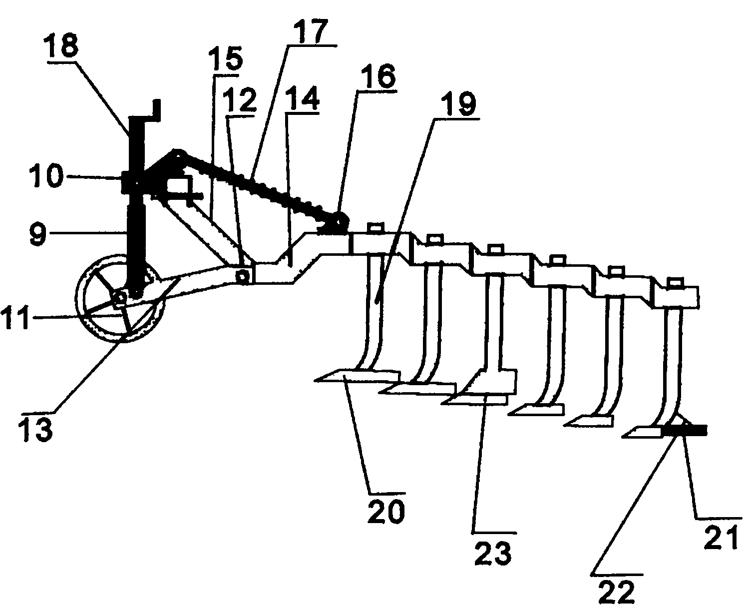
[0014] The layered cutting tillage machine includes a suspension hanger 8, a front beam 1 and a clamp 6, a rear beam 2 and a clamp 6, a straight beam 3 and a clamp 6, a sharp curved beam 4, a vertical support for ground wheels 9, a Wheel 11, pull head swing shaft 12, ground wheel alignment bracket 13, ground wheel depth adjustment screw 18, ground wheel adjustment support 10, square card 5, smooth pull beam crank arm 15, telescopic rod and spring 17, adjustment support 16. Sharply bent beam puller seat 7, sharply bent beam puller 14, plow column 19, plow share 20, soil divider 23, plow heel 21, plow heel support 22, characterized in that the front row beam 1 and the rear row beam 2 is connected with the straight beam 3, and the sharply bent beam 4 is respectively fixed and connected to the front row beam 1 and the rear row beam 2 through the sharply bent beam pull head 14 and the clamping plate 6, and is uniformly fixed on the sharply bent beam pull seat 7 A plurality of plow ...


PUM


Abstract

The invention provides a farming machine capable of realizing laminated cutting, which comprises a suspension hanger frame, a front-row cross beam, a front-row clamping plate, a back-row cross beam, a back-row clamping plate, a transverse straining beam, a transverse clamping plate, sharp-bending beams, a land-wheel vertical bracket, a land wheel, a pull head oscillating shaft, a transverse bracket of the land wheel, a depth adjusting screw rod of the land wheel, a land wheel adjusting support, a square clamp, a crank arm of the transverse straining beam, a telescopic rod, a spring, an adjusting support, straining seats of the sharp-bending beams, pull heads of the sharp-bending beams, plough columns, plough shares, a soil separating plate, a plough heel and a bracket of the plough heel and is characterized in that the front-row cross beam and the back-row cross beam are connected with the transverse straining beam; the sharp-bending beams are respectively fixed and connected with the front-row cross beam and the back-row cross beam through the pull heads of the sharp-bending beams and the clamping plates; a plurality of plough columns are uniformly fixed on the straining seats of the sharp-bending beams; the plough shares are fixed at the lower ends of all the plough columns; and the lateral dimensions of the plough shares sequentially narrow down from front to back, and the heights of the plough shares are gradually reduced from front to back, so that the plough shares form the laminated cutting. The farming machine has the following beneficial effects that as the farming method of gradually deepening and laminated cutting by the plurality of plough shares is adopted, the ideal farming depth and the ideal clod breaking effect can be achieved, the farming resistance is obviously reduced, repeated operations such as turning up the soil, deeply loosening the soil, ridging, rotary tillage, seeding, fertilizing and the like can be completed at one time; therefore.

Description

technical field [0001] The invention relates to an agricultural farming machine, especially one that can be used for deep plowing, subsoiling, ridging, sowing, fertilization, substituting harrowing, substituting rotation, intertillage, topsoil immovability, subsoil immovability, and complete breaking The plow bottom layer is a multi-purpose layered cutting tillage machine that can be completed in one operation. Background technique [0002] At present, in the cultivation process of the farmland, it is impossible to change the one-plow tillage mode. During the cultivation, the soil block is large, the resistance is large, it is laborious and time-consuming, and the cost increases. The ground must be harrowed and turned, and the trenches left must be leveled, but most of them are not deep enough and the broken soil is not good enough to store water and moisture, increase ground temperature, dissipate cold, and promote root growth and crop growth. The ideal effect, this proble...

Claims


Application Information

Patent Timeline
IPC IPC(8): A01B3/46A01B15/04
Inventor 乔生
Owner 乔生
Learn More