


Quick Research
Generate reliable direction feasibility study reports for your R&D in just a few steps.

Technical Q&A
Discover and master advanced knowledge NOW. Basics, ideas, possibilities, all at once.

Find Solutions
As an expert in R&D theories, this can generate solutions to your technical problems instantly.

Evaluate Feasibility
Analyze your overall solution with one click, know your potential R&D risks in advance.

Monitor Landscape
Get weekly tech updates, stay abreast of the latest tech innovations and key insights.
Repetitive controller and control method thereof and feedback control system
A technology of repetitive controllers and feedback channels, applied in general control systems, control/regulation systems, electric controllers, etc., can solve problems such as the inability to meet the requirements of system control performance and reduce the stability margin of the control system
- Summary
- Abstract
- Description
- Claims
- Application Information
AI Technical Summary
Problems solved by technology
Method used
Image


Examples
specific Embodiment approach 1
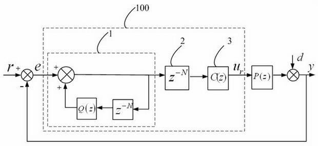
[0034] Such as figure 2 As shown, it is a structural diagram of the repetitive controller in this specific embodiment, including an internal model part 4 , a cycle delay module 5 , a first compensation module 6 and a specific frequency gating module 7 . Specific frequency gating module 7 is frequency selection module , for the error signal Specific harmonics in the frequency selection, it is connected in series with the internal model part 4, the cycle delay module 5, and the first compensation module 6, and is set at the input end of the internal model part 4.
[0035] Wherein, the internal model part 4 is a first internal model, including an adding loop 41 , an internal model filter module 42 and an internal model period delay module 43 . The internal model filtering module 42 is , It can be a filter or a constant less than 1. The internal model period delay module 43 is . The first input end of the adding loop 41 is the input end of the internal model part 4, a...
specific Embodiment approach 2
[0045] The difference between this specific embodiment and the first specific embodiment is: the frequency selection module in this specific embodiment Set at the output end of the first compensation module 6, and the frequency selection module in the specific embodiment one Set at the input end of the internal model part 4.
[0046] The repeating controller in this specific embodiment is such as Figure 4 as shown, Figure 4 Each module and implementation mode 1 figure 2 The corresponding modules are the same, only the position of the specific frequency gating module 7 is different. but Figure 4 The transfer function of the repeated controller shown is still the same as figure 2 The transfer function of the repeated controller shown is the same, still the expression (2) above. therefore, Figure 4 The shown repetitive controller still achieves specific harmonic cancellation.
[0047] In addition, from the above analysis, the specific frequency gating module 7 is ...
specific Embodiment approach 3
[0048] The difference between this specific embodiment and the first specific embodiment is: the frequency selection module in this specific embodiment It is located on the forward channel of the internal model part 4, and the frequency selection module in the specific embodiment one Set at the input end of the internal model part 4.
[0049] The repeating controller in this specific embodiment is such as Figure 5 as shown, Figure 5 Each module and implementation mode 1 figure 2 The corresponding modules are the same, only the position of the specific frequency gating module 7 is different. frequency selection module Taking the discrete cosine transform (DCT) filter as an example, at this time, the transfer function expression of the repetitive controller is:
[0050] (3)
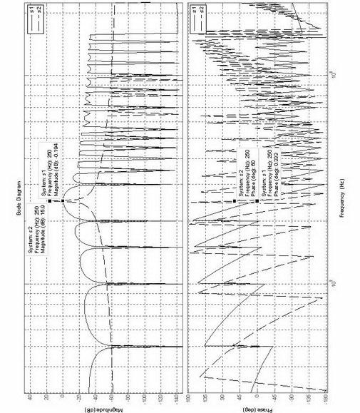
[0051] right Figure 5 The repeated controller shown is simulated, and the parameter settings are the same as those in the specific implementation mode 1. figure 2 The parameter settings...
PUM
 Abstract
Description
Claims
Application Information
 - R&D Engineer
- R&D Manager
- IP Professional
- Industry Leading Data Capabilities
- Powerful AI technology
- Patent DNA Extraction
Browse by: Latest US Patents, China's latest patents, Technical Efficacy Thesaurus, Application Domain, Technology Topic, Popular Technical Reports.
© 2024 PatSnap. All rights reserved.Legal|Privacy policy|Modern Slavery Act Transparency Statement|Sitemap|About US| Contact US: help@patsnap.com