
Electrical terminal

A technology of electrical wiring and terminals, applied in the direction of conductive connection, circuit, connection, etc., can solve the problem that the logo is invisible to the user, etc.

Active Publication Date: 2011-07-20
PHOENIX CONTACT GMBH & CO KG
View PDF5 Cites 42 Cited by
  • Summary
  • Abstract
  • Description
  • Claims
  • Application Information

AI Technical Summary

Problems solved by technology

However, this has the disadvantage that, in the open state of the actuator, the marking is not visible to the user, since the operating part is swiveled upwards in this state and thereby swivels the surface of the actuator out of the user's field of vision.

Method used


Image

  • Electrical terminal
  • Electrical terminal
  • Electrical terminal

Examples


Embodiment Construction

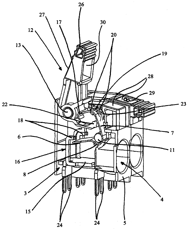
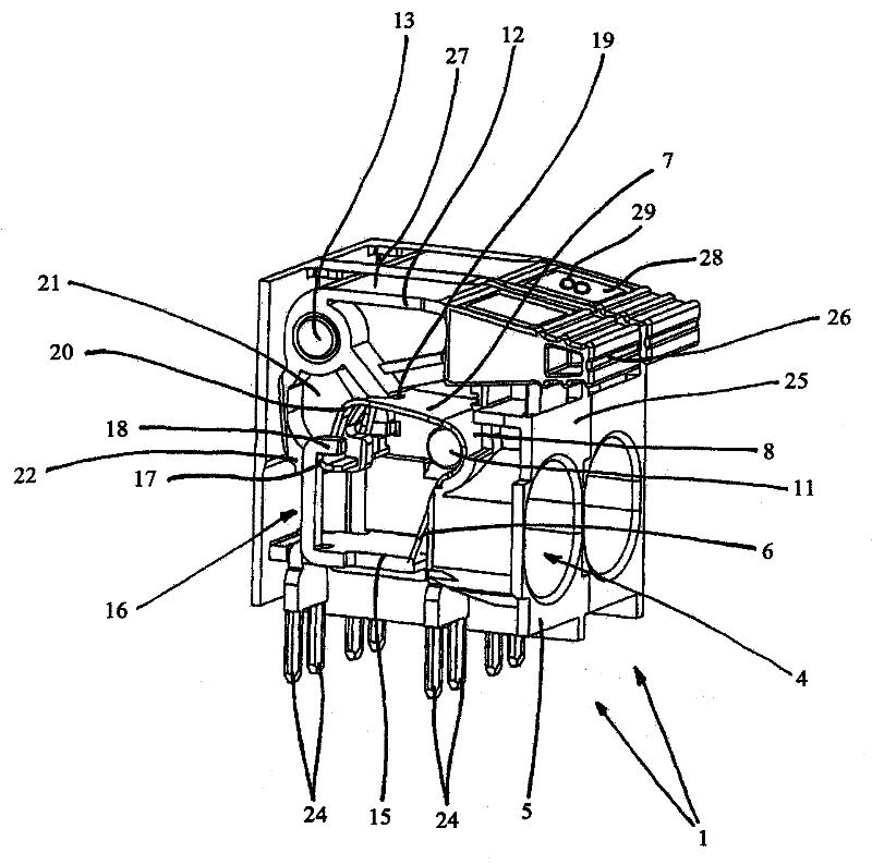
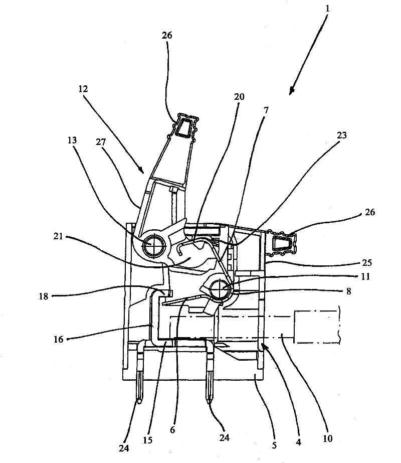
[0053] The figure shows an electrical connection terminal 1 which is firstly formed from a clamping spring 2 and a metal part 3 . Both the clamping spring 2 and the metal part 3 are here formed from simple punched or bent parts, wherein the same material does not have to be used for the clamping spring 2 and the metal part 3 . The clamping spring 2 and the metal part 3 are located in a housing 5 with a conductor insertion opening 4 , which housing is made of insulating material, in particular plastic.

[0054] The clamping spring 2 has a clamping arm 6, an actuating arm 7 and a back 8 connecting the two arms 6, 7 to each other, wherein the clamping arm 6 and the metal part 3 form a clamping point 9 for only exist image 3 The stripped conductor 10 to be connected is shown in . Inside the housing 5 there is a support pin 11 on which the clamping spring 2 is pivotably arranged such that the clamping spring 2 can move from the first (open) position ( figure 1 and 3 ) swings t...


PUM


Abstract

The invention relates to an electrical terminal (1) comprising a clamping spring (2), a metal part (3), and a housing (5) accommodating the clamping spring (2) and the metal part (3), and comprising at least one conductor insertion opening (4), wherein an actuation element (12) supported in the housing (5) is provided for opening and closing the terminal (1), wherein the actuation element (12) comprises a handle (27), through which the actuation element (12) can be transferred into an opened and into an closed state. A labeling area (28), which is arranged in such a way that the labeling area(28) is visible to a user at any time, is provided for marking the terminal (1).

Description

technical field [0001] The invention relates to an electric terminal. Background technique [0002] Electrical terminals have a variety of structural forms. For this purpose, the connection terminals can be formed, for example, as so-called printed terminals for connecting the electrical conductors to a printed circuit board, or as terminal boards for the connection of other conductors. [0003] The clamping spring can be a ring-shaped clamping spring, the so-called tension spring clamp, or a U-shaped or V-shaped clamping spring, the so-called helical torsion spring, which can be inserted directly into the , That is to say, it is inserted into a solid conductor or a conductor with a skin without the clamping position having to be opened in advance with a tool. With known ring-shaped tension springs—as the name implies—the conductor to be connected is pulled by the clamping arm relative to the conductor rail. In addition, in contrast to this, with U-shaped or V-shaped clam...

Claims


Application Information

Patent Timeline
Patent Type & Authority Applications(China)
IPC IPC(8): H01R4/48H01R9/24
CPCH01R9/2475H01R13/465H01R4/4836H01R4/4821H01R4/483
Inventor 阿恩特·沙夫迈斯特
Owner PHOENIX CONTACT GMBH & CO KG
Learn More