


Quick Research
Generate reliable direction feasibility study reports for your R&D in just a few steps.

Technical Q&A
Discover and master advanced knowledge NOW. Basics, ideas, possibilities, all at once.

Find Solutions
As an expert in R&D theories, this can generate solutions to your technical problems instantly.

Evaluate Feasibility
Analyze your overall solution with one click, know your potential R&D risks in advance.

Monitor Landscape
Get weekly tech updates, stay abreast of the latest tech innovations and key insights.
Steam turbine
A technology of steam turbines and impellers, applied in mechanical equipment, engine components, machines/engines, etc., can solve problems such as unclear steam piping cooling passages through the casing, difficult direct connection of steam piping, and inability to ensure the uniformity of cooling steam pressure. , to achieve the effect of improving thermal efficiency
- Summary
- Abstract
- Description
- Claims
- Application Information
AI Technical Summary
Problems solved by technology
Method used
Image


Examples
Embodiment approach 1
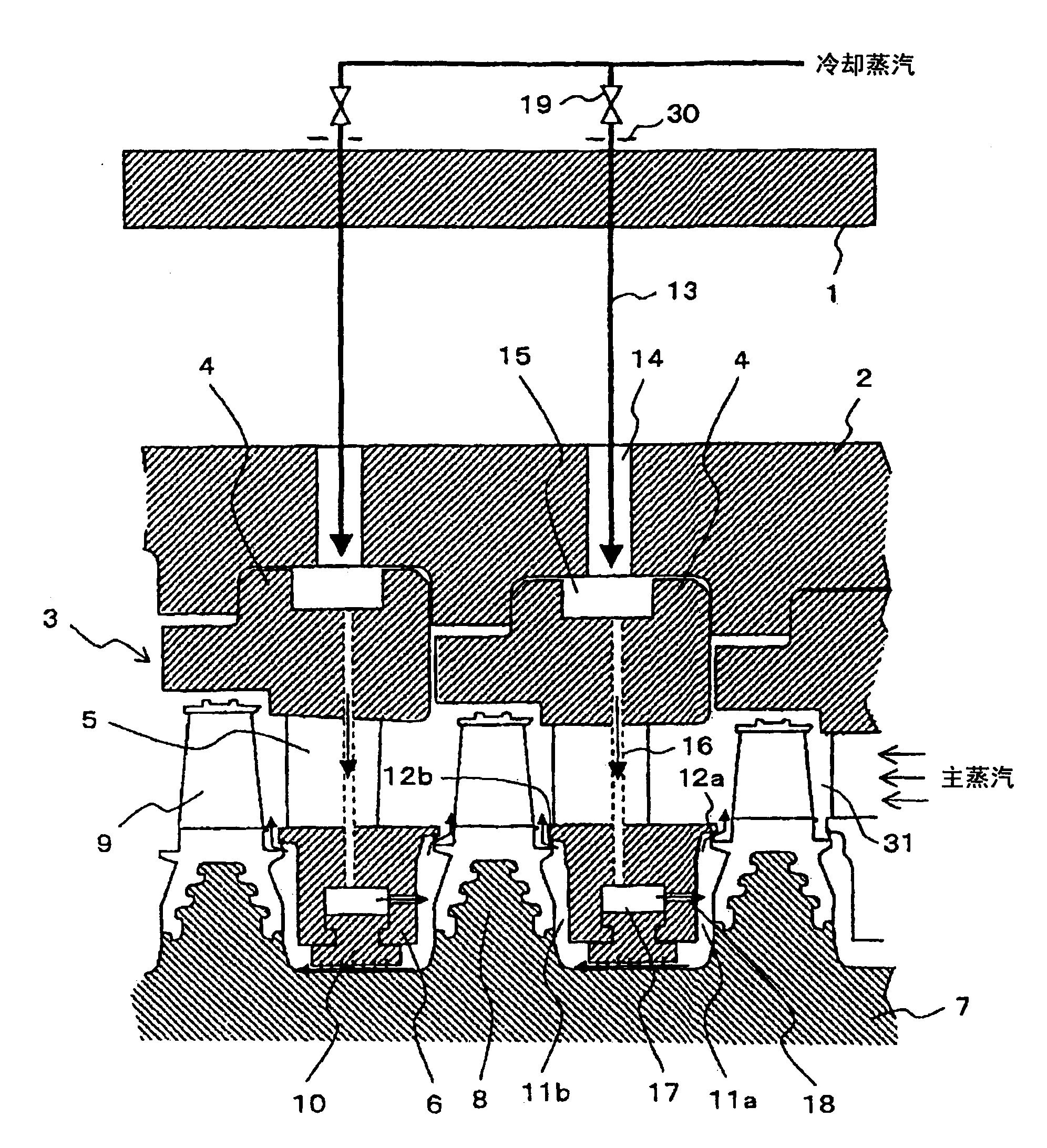
[0023] figure 1 It is an axial sectional view showing the steam turbine according to Embodiment 1 of the present invention.
[0024] exist figure 1 In , the right side of the main steam passage portion 31 is upstream, and the left side is downstream. The stationary side of the steam turbine is composed of an outer casing 1 , an inner casing 2 , and partitions 3 of various stages. The partitions 3 include an outer ring 4 , a plurality of stationary blades 5 and an inner ring 6 . The rotating side is constituted by an impeller-type rotor 7 in which rotor impellers 8 are formed in stages, and a plurality of moving blades 9 implanted and fixed on the rotor impellers 8 . In addition, the space between the inner ring 6 and the front and rear rotor wheels 8 forms the wheel space 11a, 11b, and the wheel space sealing parts 12a, 12b such as sealing sheets are used between this space and the main steam passage part 31 to prevent the main steam from flowing into the wheel space. 11a, ...
Embodiment approach 2
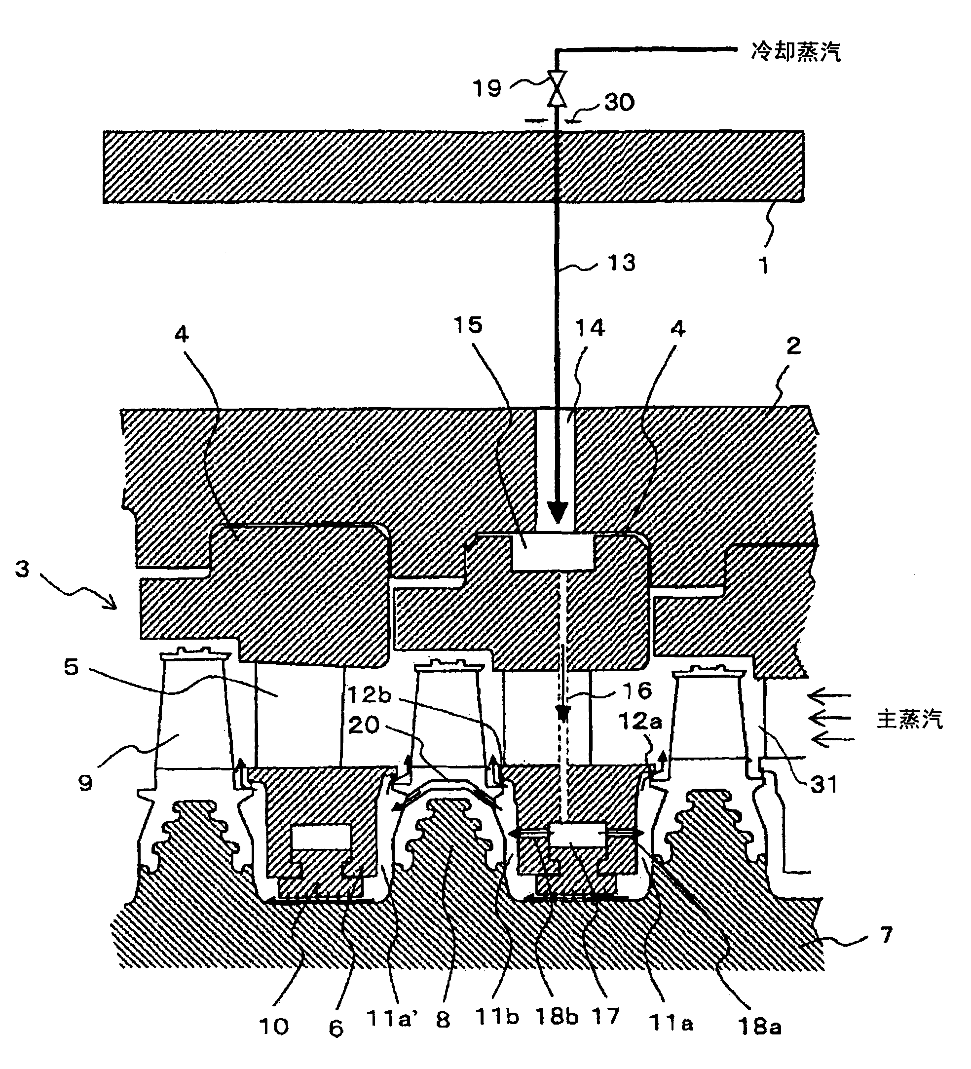
[0048] image 3 It is an axial sectional view showing a steam turbine according to Embodiment 2 of the present invention.
[0049] In Embodiment 1, cooling steam is supplied to the outer ring cavity 15 at each stage to cool the outer ring cavity 15 independently; however, in this embodiment, the cooling steam supplied to the upstream stage is also configured to perform cooling on the adjacent downstream stage. Stage cooling, the purpose of which is to simplify the structure.
[0050] The configuration of the stage to which cooling steam is supplied from the outer ring side is the same as that of Embodiment 1, and is supplied from the balance hole 20 provided in the moving blade fixing portion to the impeller space 11a' on the upstream side of the stator blade of the downstream stage. In addition, the inner ring 6 has bidirectional blowout holes 18 a and 18 b directed toward the wheel space 11 a on the upstream side of the stator blades and the wheel space 11 b on the downstre...
Embodiment approach 3
[0055] Figure 4 It is an axial sectional view showing a steam turbine according to Embodiment 3 of the present invention.
[0056] In this embodiment, compared to the above-mentioned second embodiment, instead of the balance hole 20, a plurality of internal rotor communication holes 21 are provided in the rotor over the entire circumference in the circumferential direction. It communicates with the wheel space 11a' on the upstream side of the stator blades of the adjacent downstream stage. In addition, the outlet hole 18b on the wheel space 11b side on the downstream side of the stator vane in Embodiment 2 can be omitted.
[0057] Next, the operation of this embodiment will be described.
[0058] Part of the cooling steam directly flows from the wheel space 11a on the upstream side of the stator blades to the wheel space 11a' on the upstream side of the stator blades on the downstream stage, and cools the rotor 7 on the downstream stage in the same manner as in the second e...
PUM
 Abstract
Description
Claims
Application Information
 - R&D Engineer
- R&D Manager
- IP Professional
- Industry Leading Data Capabilities
- Powerful AI technology
- Patent DNA Extraction
Browse by: Latest US Patents, China's latest patents, Technical Efficacy Thesaurus, Application Domain, Technology Topic, Popular Technical Reports.
© 2024 PatSnap. All rights reserved.Legal|Privacy policy|Modern Slavery Act Transparency Statement|Sitemap|About US| Contact US: help@patsnap.com