
Strong magnetic variation gradient magnetic separator of inner permanent magnetic cylinder

A gradient magnetic separation and inner cylinder technology, applied in the direction of magnetic separation, solid separation, chemical instruments and methods, etc., can solve the problems of low operating safety factor, no fine-tuning function of adjusting the magnetic gap distance, and affecting the separation effect, etc., to achieve Improve the effect of sorting index and grade

Inactive Publication Date: 2011-07-20
INST OF ROCK & SOIL MECHANICS CHINESE ACAD OF SCI
View PDF6 Cites 27 Cited by
  • Summary
  • Abstract
  • Description
  • Claims
  • Application Information

AI Technical Summary

Problems solved by technology

Since the fixed excitation device is set with a high magnetic permeability material at a certain distance outside the magnetic gap, the magnetic force is proportional to the action area, and the strong magnetic force caused by the excitation increases the magnetic flux of the magnetic gap, so that the excitation device is used in the equipment assembly process. Risk and difficulty, low safety factor in operation, so the structural device used in the magnetic gap excitation is usually strengthened and locked, and there is no fine-tuning function to adjust the magnetic gap distance, which affects the separation effect

Method used


Image

  • Strong magnetic variation gradient magnetic separator of inner permanent magnetic cylinder
  • Strong magnetic variation gradient magnetic separator of inner permanent magnetic cylinder
  • Strong magnetic variation gradient magnetic separator of inner permanent magnetic cylinder

Examples


Embodiment Construction

[0020] The following is a further detailed description of the permanent magnet inner cylinder strong magnetic variable gradient magnetic separator of the present invention in conjunction with the accompanying drawings:

[0021] see Attachment.

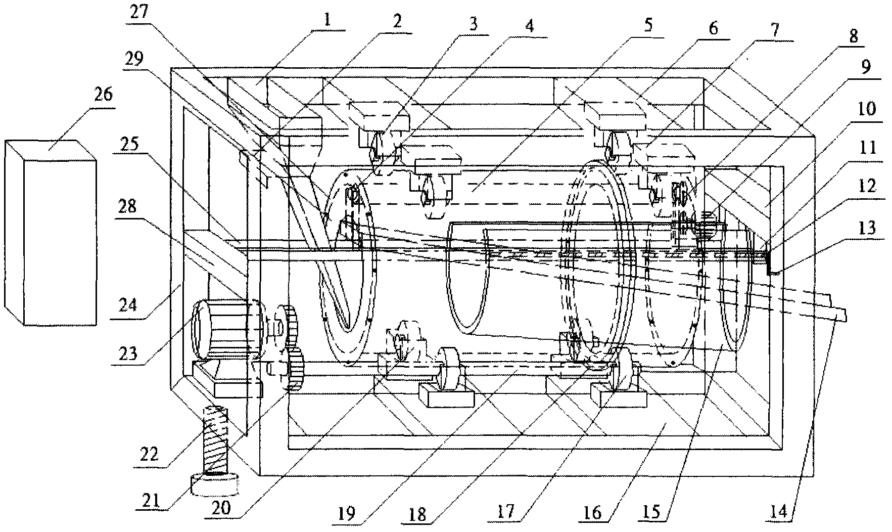
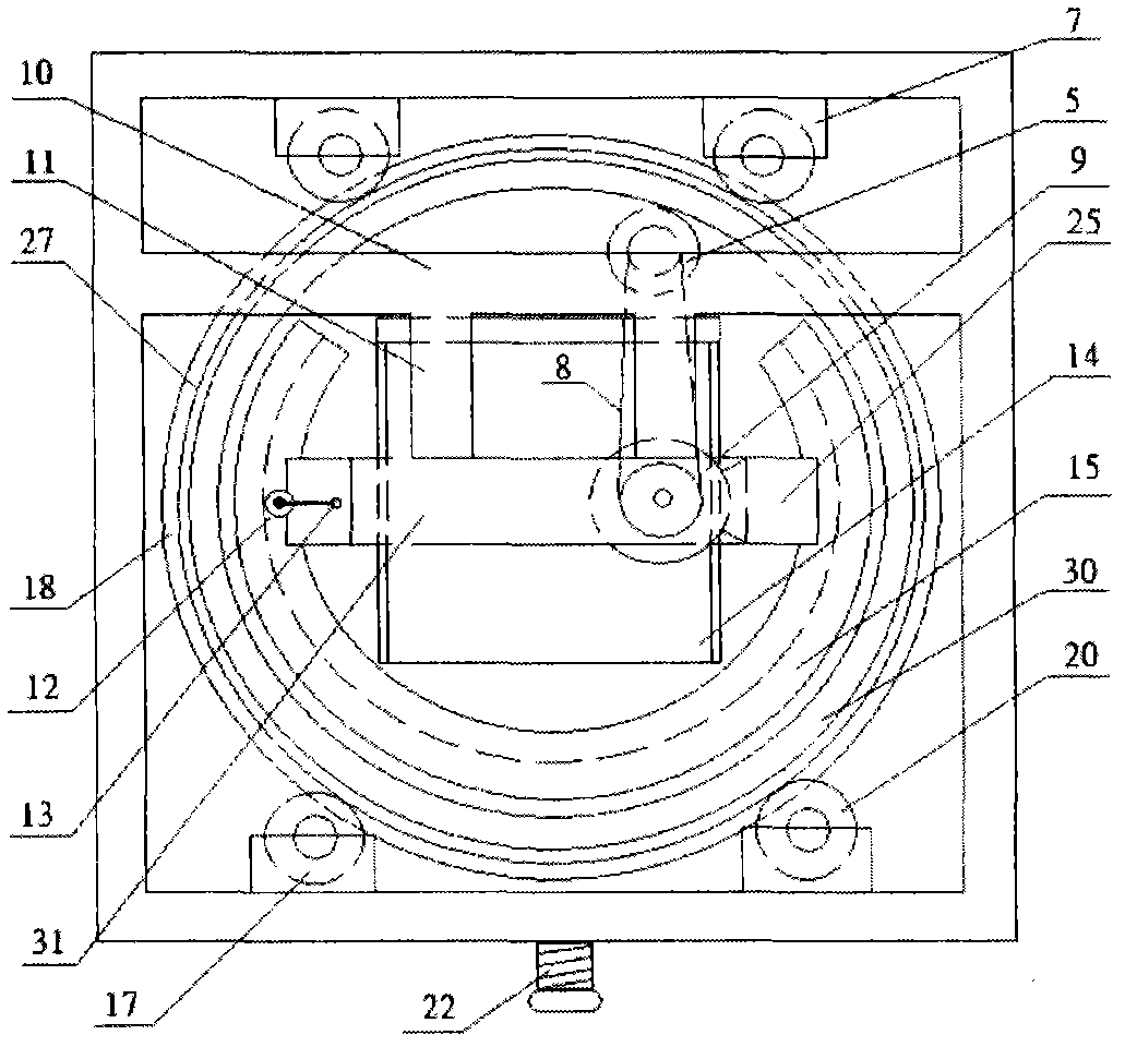
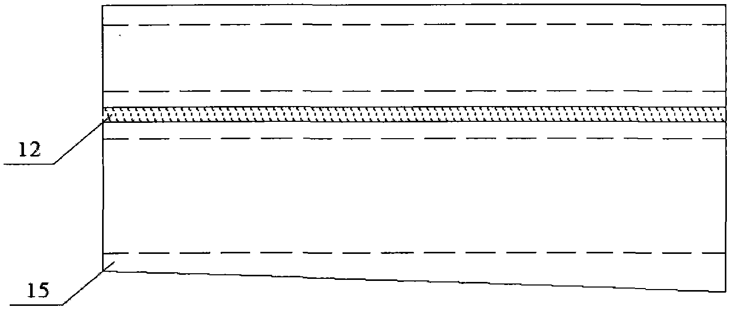
[0022] The present invention solves its technical problem. The specific implementation method is: the variable gradient magnetic separator in the permanent magnet inner cylinder is composed of a blanking box 1, a blanking amount control gate 2, a roller 3, a wool roller support 4, a blanking wool roller 5, and an upper bearing Beam 6, roller base 7, top roller belt pulley 8, top roller motor 9, right beam 10, inner bracket suspension rod 11, exciter moving screw 12, screw rotation handle 13, concentrate discharge chute 14, exciter 15 , Lower load-bearing beam 16, driving roller 17, flange 18, transmission connecting rod 19, passive roller 20, connecting rod gear 21, inclination adjustment screw 22, power motor 23, frame 24, inner suppo...


PUM


Abstract

The invention relates to a strong magnetic variation gradient magnetic separator of an inner permanent magnet cylinder, belonging to the mineral machinery. The strong magnetic variation gradient magnetic separator of the inner permanent magnet cylinder comprises a permanent magnet roller, a control cabinet, an excitation body, a tilt adjusting screw rod of the magnetic separator, a frame, a material discharge box, a material discharging quantity control shutter, a material discharge roller, a roller support idler wheel, an inner bracket beam, a material discharge groove, a bracket, an anti-skid flange plate for the permanent magnet roller, a power motor, an excitation body moving screw rod, and the like. The strong magnetic variation gradient magnetic separator of the inner permanent magnet cylinder has functions of strengthening magnetic field intensity and changing magnetic field gradient, and can further enhance the grade and the yield of the magnetic separation of low magnetic susceptibility mineral power which is difficult to select. The strong magnetic variation gradient magnetic separator has the advantages of compact structure, and convenience for installation and operation, and is suitable for separating various kinds of weak magnetic rare metal mineral powders or exhausting impurities and purifying nonmetal mineral powders. The strong magnetic variation gradient magnetic separator can be separately applied to a dry separation technology or a wet separation technology, and is a permanent magnet high-gradient technical device which can replace an electromagnetic separator with high energy consumption and high gradient.

Description

technical field [0001] The invention discloses a permanent magnetic inner tube strong magnetic variable gradient magnetic separator, which belongs to the category of mineral machinery. The magnetic separator has the functions of strengthening the magnetic field strength and changing the magnetic field gradient in the permanent magnetic roller, and can further improve the low The grade and yield of magnetic separation of rare ore powders with specific magnetic susceptibility are suitable for the separation of various weak magnetic rare metal ore powders or the impurity removal and purification of non-metallic ore powders. They can be applied to dry or wet separation processes respectively. Permanent magnet high gradient magnetic separation equipment of high energy consumption high gradient electromagnetic separator. Background technique [0002] Mineral resources are non-renewable resources. The energy crisis is a major problem facing the world in the 21st century. With the d...

Claims


Application Information

Patent Timeline
Patent Type & Authority Applications(China)
IPC IPC(8): B03C1/12
Inventor 潘志强薛强李江山胡竹云
Owner INST OF ROCK & SOIL MECHANICS CHINESE ACAD OF SCI
Learn More