
Beads threading machine

A bead threading and threading technology, which is applied in the direction of jewelry, decorative chains, tools for passing ribbons, etc., can solve the problems that beads cannot be threaded, and various beads with different outer diameters cannot be connected, so as to achieve easy threading and improve production The effect of degrees of freedom

Inactive Publication Date: 2011-07-20
EPOCH CO
View PDF11 Cites 6 Cited by
  • Summary
  • Abstract
  • Description
  • Claims
  • Application Information

AI Technical Summary

Problems solved by technology

However, this bead threading device is used to make decorations by connecting beads of the same diameter, and there is a problem that it cannot connect various kinds of beads with different outer diameters.
[0005] Moreover, although the bead threading device described in Patent Document 2 can select a variety of balls for threading, it is necessary to guide the balls to the landing port. Therefore, the balls for threading are limited to shapes that are easy to roll or slide.
Moreover, the bead threading device must always fix the falling direction, therefore, it is not possible to thread spherical balls and complex-shaped balls.

Method used


Image

  • Beads threading machine
  • Beads threading machine
  • Beads threading machine

Examples


Embodiment Construction

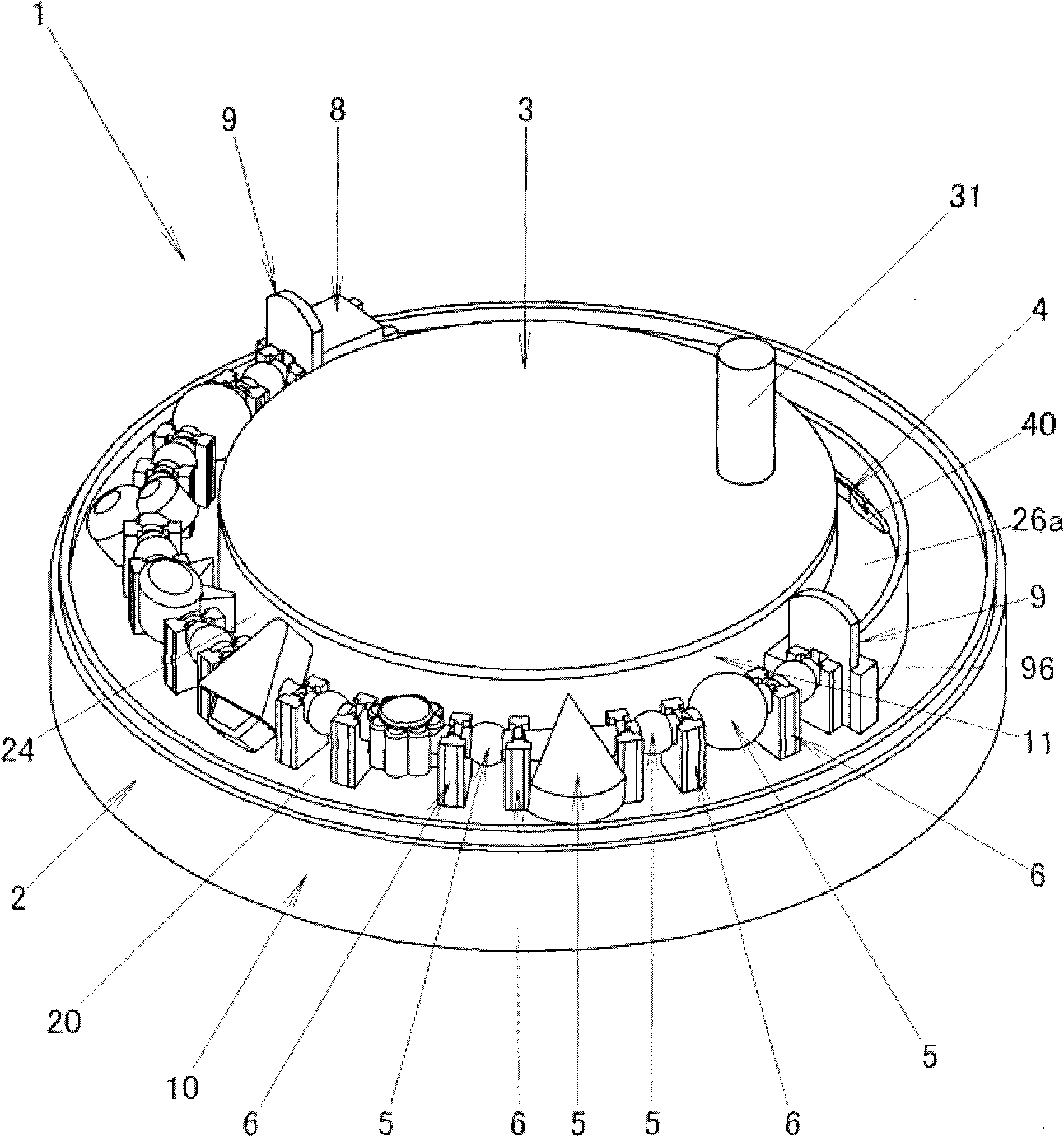
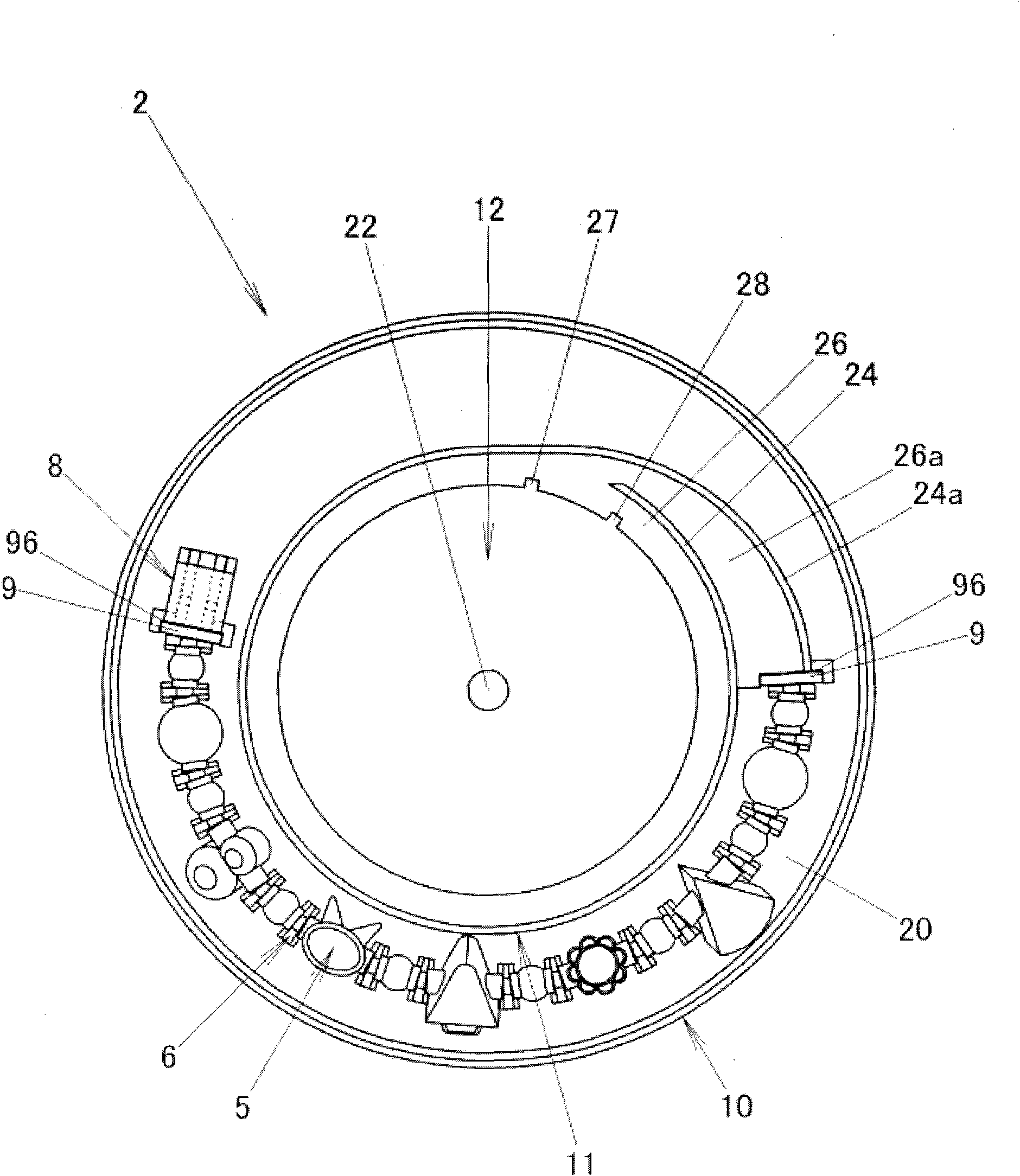
[0043] The configuration for implementing the present invention will be described below. The bead threading device 1 is a device for threading 7 a plurality of beads 5. The bead 5 has a bead hole 50 for passing through the bead 5 and a ring-shaped thread protruding outward from both ends of the bead hole 50. protrusion 56 .

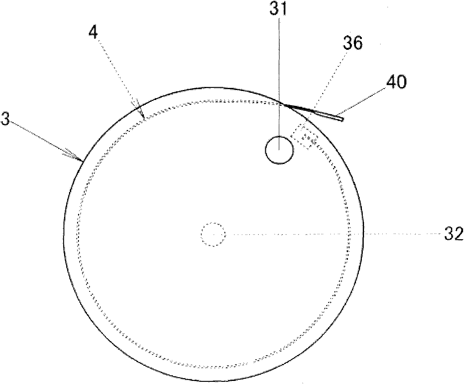
[0044] Furthermore, this bead threading device 1 includes a circular main body 2 , a plurality of support parts 6 , a thread holding part 8 , an insertion member 4 , a guide path 26 a , a rotating plate 3 , and a storage path 26 . The plurality of support portions 6 are arranged at predetermined intervals in the circumferential direction of the main body 2 above the main body to support the annular protrusion 56 of the ball 5 . The wire holding portion 8 is arranged on the wire inlet side, that is, one end side of a support portion row formed by a plurality of support portions 6 arranged in the circumferential direction. The insertion member 4 is provid...


PUM


Abstract

The invention provides a beads threading machine with which a thread can easily be put through a plurality of beads of various shapes, The beads threading machine for threading a plurality of beads each having annular projecting portions which project outwards from end portions of the bead hole, the beads threading machine comprises: a plurality of supporting portions which are disposed at predetermined intervals along a circumferential direction of a circular main body on the main body to thereby support the annular projecting portions of the beads; a thread holding portion which is disposed at one end side of the row of supporting portions; an insertion member having at a distal end thereof a hook portion on which a thread disposed in the thread holding portion is hooked; a guide path for guiding the insertion member at the other end side which is opposite to the end side of the row of the supporting portion; a rotary plate having a fixing portion where a rear end of the insertion member is fixed; and an accommodation path for accommodating the insertion member along the circumferential edge of the rotary plate, wherein by rotating the rotary plate in a forward direction, the insertion member is inserted through the bead holes to thereby dispose the hook portion in the thread holding portion, whereas by rotating the rotary plate in a reverse direction, a thread disposed in the thread holding portion is caused to be hooked on the hook portion so that the thread hooked on the hook portion is put through the bead holes.

Description

technical field [0001] The invention relates to a bead threading device for threading a bead ball. Background technique [0002] In the past, various devices for threading beads to make ornaments such as necklaces and bracelets have been proposed. For example, in Japanese Patent Application Laid-Open No. 2003-213552 as Patent Document 1, it is proposed to use a plurality of clamping devices having a pair of opening and closing clamping members to clamp the shaft passing through the bead hole of the ball, and The abutting member for opening and closing a plurality of clamping members in pairs is arranged on the top, and the clamping members are sequentially opened and closed by the rotation of the rotating shaft, so as to maintain the shaft vertically. At the same time, by making the clamping part Open and close sequentially, the bead ball that the shaft passes through the bead hole descends along the shaft, and the thread hooked by the lower end of the shaft pass through th...

Claims


Application Information

Patent Timeline
Patent Type & Authority Applications(China)
IPC IPC(8): A44C27/00A44C5/00A44C11/00
CPCD04D11/00D04D1/04
Inventor 神山圭
Owner EPOCH CO
Learn More