RF power splitter for magnetic resonance system

A power divider and radio frequency power technology, which is applied to waveguide devices, electrical components, connection devices, etc., can solve the problems of complex structure, power loss, etc., and achieve the reduction of the number of components, the reduction of manufacturing costs, and the simplification of design and tuning Effect

Inactive Publication Date: 2011-07-13
KONINK PHILIPS ELECTRONICS NV
View PDF5 Cites 6 Cited by
  • Summary
  • Abstract
  • Description
  • Claims
  • Application Information

AI Technical Summary

Problems solved by technology

Butler matrices also have significant power losses and are complex to construct because each of the N / 2+N / 4...+N / N couplers and corresponding cable lengths must be adjusted to obtain the required impedance and phase matching

Method used


Image

  • RF power splitter for magnetic resonance system
  • RF power splitter for magnetic resonance system
  • RF power splitter for magnetic resonance system

Examples


Embodiment Construction

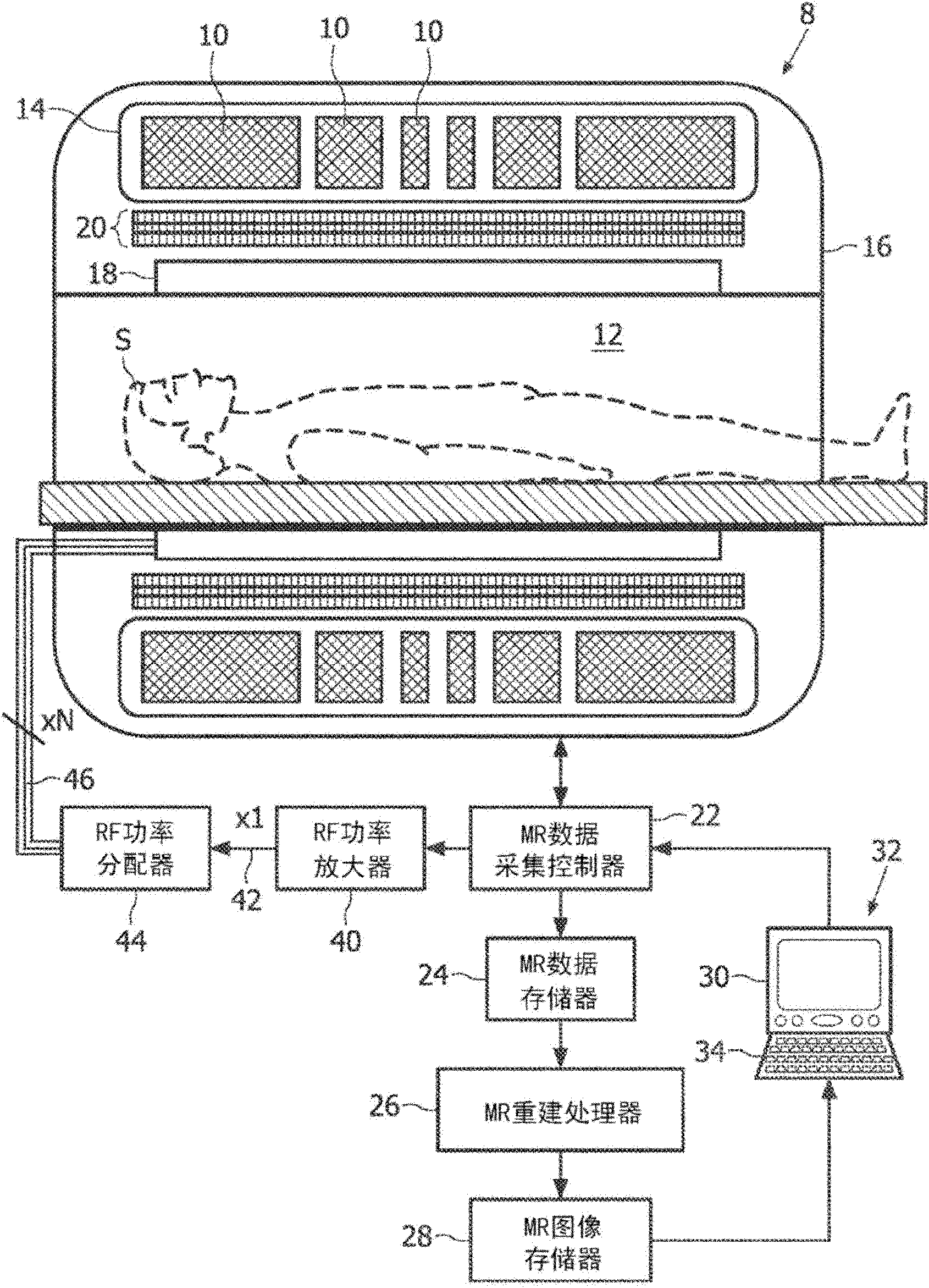
[0021] refer to figure 1 , the magnetic resonance (MR) scanner 8 includes a static main (B 0 ) The main magnet 10 of the magnetic field. In the illustrated embodiment, the main magnet 10 is a superconducting magnet disposed in a cryogenic vessel 14 utilizing helium or another cryogenic fluid; alternatively a normally conducting or permanent main magnet may be used. In the illustrated embodiment, the magnet assemblies 10, 14 are disposed within a generally cylindrical scanner housing 16 that defines the examination region 12 as a cylindrical bore; alternatively, other geometries, such as open MR geometric shapes. Magnetic resonance is excited and detected by one or more radio frequency coils, such as the multi-element body coil 18 shown, or one or more local coils or coil arrays, such as head coils or chest coils. The excited magnetic resonance is spatially encoded, phase shifted and / or frequency shifted or otherwise manipulated by magnetic field gradients selectively genera...


PUM


Abstract

A radio frequency transmission system for a magnetic resonance system includes a radio frequency power amplifier (40) generating an input radio frequency signal that excites magnetic resonance in target nuclei and is designed for feeding an impedance Zo, a multi-channel radio frequency coil (18) having N radio frequency channels where N>1, and a power splitter (44) including (i) a parallel radio frequency connection point (50) at which the N channels of the radio frequency coil are connected in parallel to define an output impedance at the parallel radio frequency connection point, and (ii) an impedance matching circuit (54) connecting the radio frequency power amplifier with the radio frequency connection point and configured to provide impedance matching between the radio frequency power amplifier and the output impedance at the connection point.

Description

technical field [0001] The following relates to the field of radio frequency power, the field of electronics, the field of magnetic resonance, and related fields. The following is described by way of example application to magnetic resonance systems for imaging, spectroscopy, and the like. However, the following will find more general application generally in radio frequency power circuits, generally in microwave circuits and devices, and the like. Background technique [0002] In a typical magnetic resonance system used for imaging or spectroscopy, a radio frequency power amplifier is used for the transmit phase (ie, for magnetic resonance excitation). The output of the amplifier is fed into two channels of the quadrature "integral" transmit coil, ie into the 0° phase "I" channel and the 90° phase "Q" channel. The coupling of the amplifier to the I and Q channels of the quadrature transmit coil is typically achieved using so-called "hybrid" couplers that introduce a 90° p...

Claims


Application Information

Patent Timeline
Patent Type & Authority Applications(China)
IPC IPC(8): H01P5/12
CPCH01P5/12
Inventor C・芬德科里
Owner KONINK PHILIPS ELECTRONICS NV
Why Eureka
Try Eureka