Composite-rotor brushless double-fed alternating current motor

A brushless double-fed, AC motor technology, applied in asynchronous induction motors, electrical components, electromechanical devices, etc., can solve the problems of complex manufacturing process, large loss of rotor windings, poor modulation effect, etc., and achieves simple structure and improved performance. The effect of price ratio

Active Publication Date: 2013-01-30
广东华拿东方能源有限公司
View PDF0 Cites 0 Cited by
  • Summary
  • Abstract
  • Description
  • Claims
  • Application Information

AI Technical Summary

Problems solved by technology

[0003] The advantage of the above-mentioned wound rotor brushless double-fed motor is that the rotor manufacturing process is similar to that of the traditional wound rotor induction motor, which is convenient for processing and manufacturing. The disadvantage is that the rotor winding loss is large and the material used is more
The advantages of axial lamination and radial lamination reluctance rotor brushless doubly-fed motors are that the rotor structure has a good modulation effect on the magnetic field generated by the stator winding current, and the rotor loss is small. The disadvantage is that the manufacturing process is complicated, not only the cost is high, And it is difficult to process and manufacture the rotor of large brushless doubly-fed motor
The salient pole reluctance rotor with slots only on the rotor core has the advantages of simple structure and low cost, but its structure has a poor modulation effect on the magnetic field generated by the stator winding current, resulting in poor performance of the brushless double-fed motor

Method used


Image

  • Composite-rotor brushless double-fed alternating current motor
  • Composite-rotor brushless double-fed alternating current motor
  • Composite-rotor brushless double-fed alternating current motor

Examples


Embodiment Construction

[0022] To further illustrate the present invention, the composite rotor brushless doubly-fed AC motor of the present invention will be described in more detail below in conjunction with embodiments.

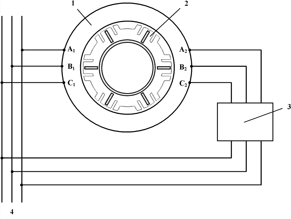
[0023] figure 1 It is a schematic diagram of the composite rotor brushless double-fed AC motor of the present invention, where 1 is the motor stator, 2 is the rotor, 3 is the controller, and 4 is the AC power supply. Two sets of independent symmetrical windings are placed in the core slot of the motor stator 1. The power winding outlet terminals are represented by A1, B1, C1, and the control winding outlet terminals are represented by A2, B2, C2. The connection relationship of the windings is: the outlet terminals A1, B1, and C1 of the power winding are connected to the AC power source 4, and the outlet terminals A2, B2, C2 of the control winding are connected to the AC power source 4 through the controller 3.

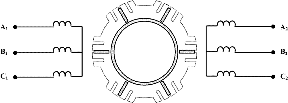
[0024] figure 2 It is a schematic diagram of the stator winding structur...


PUM


Abstract

The invention discloses a composite-rotor brushless double-fed alternating current motor which comprises a stator, a rotor, a rotary shaft and a controller, wherein a power winding of the stator is connected with a power supply, and a control winding is connected with the power supply through the controller. The power winding and the control winding have 2p and 2q poles respectively, wherein 2p is greater than 2q plus 2. The rotor comprises a rotor core and a magnetic isolation sleeve, the rotary shaft is made from magnetic material, and the magnetic isolation sleeve is made from non-magnetic material and is mounted between the rotor core and the rotary shaft. (p+q) inverted trapezoidal grooves are uniformly distributed on the outer edge of the rotor core; a radial open groove is arranged between every two adjacent inverted trapezoidal grooves; and a radial narrow groove is arranged between each inverted trapezoidal groove and the open groove. The rotary shaft made from the magnetic material can be replaced by a rotary shaft made from the non-magnetic material, and the magnetic isolation sleeve is cancelled at the same time. The invention has the beneficial effects that: the electromechanical energy conversion efficiency and performance of the motor are improved, the structure is simple, the cost is low, the machining process is easy, and the cost performance of the brushless double-fed motor is increased.

Description

Technical field [0001] The invention relates to an AC motor, in particular to a composite rotor brushless double-fed AC motor. Background technique [0002] In the existing single-motor brushless double-fed AC motor, two sets of windings with different pole numbers are embedded on the stator core of the motor, which are used as power windings and control windings. The rotor mainly has a wound rotor (including single-layer concentric short-circuit windings). And double-layer distributed short-pitch winding) and reluctance rotor (including axial or radial laminated reluctance rotor and salient pole reluctance rotor with cogging) structure. [0003] The advantage of the above-mentioned wound rotor brushless doubly-fed motor is that the rotor manufacturing process is similar to that of the traditional wound rotor induction motor, which is easy to process and manufacture. The disadvantage is that the rotor winding loss is large and the material is used more. The advantages of the axial...

Claims


Application Information

Patent Timeline
Patent Type & Authority Patents(China)
IPC IPC(8): H02K29/00H02K1/22H02K17/20H02K3/16
Inventor 王凤翔张岳杨华
Owner 广东华拿东方能源有限公司
Why Eureka
Try Eureka