Improvements to solar thermal collectors

A front beam and dish-shaped technology is applied in the field of dish-shaped structure of a parabolic mirror type solar heat collector, which can solve the problems of high cost, high cost of dish-shaped parts, and the mirror cannot be easily installed directly.

Active Publication Date: 2011-06-15
SUNRISE CSP PTY
View PDF0 Cites 1 Cited by
  • Summary
  • Abstract
  • Description
  • Claims
  • Application Information

AI Technical Summary

Problems solved by technology

[0005] The problem with prior art space frame designs is that the individual components are relatively expensive to manufacture, and therefore the cost of the dish is usually high
This may be acceptable for a one-piece design such as a prototype or radio telescope dish, but is too costly for use in a solar thermal plant where hundreds or thousands of individual collector dishes may be required
An additional problem is that the mirrors cannot be easily mounted directly to the space frame and must be mounted via their own single support structure
This increases the mass and cost of the overall structure

Method used


Image

  • Improvements to solar thermal collectors
  • Improvements to solar thermal collectors
  • Improvements to solar thermal collectors

Examples


Embodiment Construction

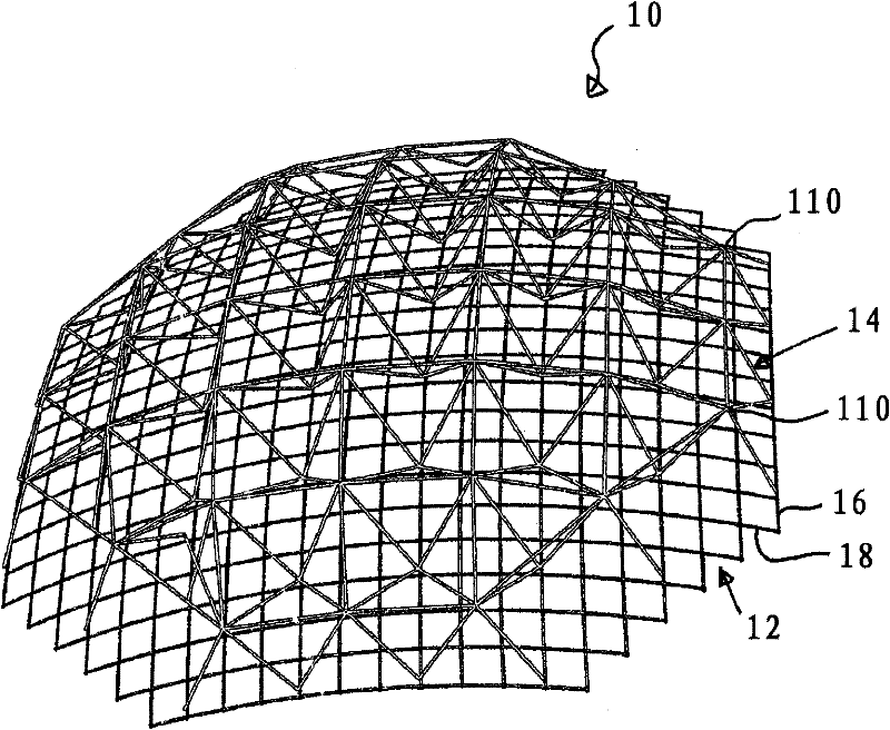
[0074] refer to Figures 1 to 15 , shows the structure of a parabolic dish 10 for use with a mirror and a jig for its construction according to an embodiment of the present invention. For clarity, mirrors are not shown in these figures, but in Figure 17 and 18 A mirror is shown.

[0075] The dish structure can be divided into a front structure 12 and a rear structure 14 .

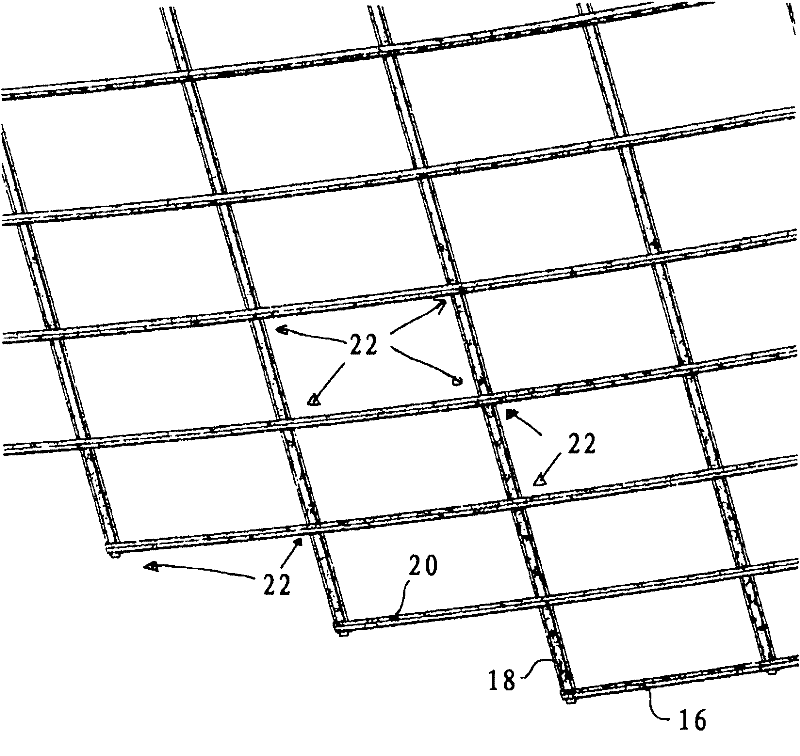
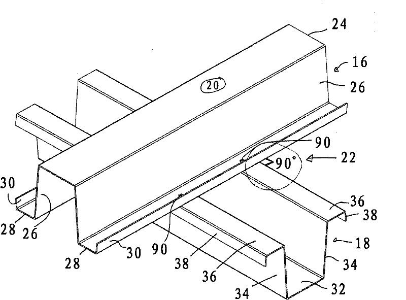
[0076] The front structure 12 is formed by a series of elongated front beams 16 arranged side by side and spaced apart. A series of elongated rear beams 18 extend substantially transversely across the rear of the front beams 16 and are also spaced apart and arranged side by side. In this embodiment, the front surface 20 of each beam provides a single mounting area on which the mirror can be mounted.

[0077] The front beams 16 are curved so that the one or more mounting areas of each front beam 16 follow an imaginary curved surface along the length of the front beams. In this case, the front surface ...


PUM


Abstract

A dish structure (10) has a virtual front surface, the front surface having a periphery, and a plurality of spaced apart non overlapping elongate front beams (16), each of which extends between two points on the periphery. Each front beam (16) has at least one mounting area (20) for receiving a reflective panel (150), the at least one mounting area (20) conforming substantially to the virtual front surface in the longitudinal direction of the front beam (16).

Description

technical field [0001] The present invention relates to dish structures, and more particularly to dish structures for solar thermal collectors of the parabolic mirror type. However, the invention is not limited to parabolic mirror type solar thermal collectors. Background technique [0002] Sunlight is a source of "renewable" energy that can be captured for human use using various technologies. One concentrating method is to use many large parabolic dishes, each supporting a mirrored surface that concentrates the light onto its own heat collector fixed relative to the mirrored surface. As the earth moves during the day, each dish is manipulated so that sunlight remains focused on the collection point. [0003] Each dish typically has a radius of about 10 to 30 metres. The mirrored surface needs to follow the desired parabolic surface with relatively high precision, making the focal area relatively small and efficient. [0004] The prior art of forming a structure of a di...

Claims


Application Information

Patent Timeline
Patent Type & Authority Applications(China)
IPC IPC(8): F24J2/46E04B1/19F24J2/00G01S1/00H01Q1/00F24S23/71
CPCY02E10/42F24J2/5203Y02E10/47F24J2/54F24J2/12F24S23/71F24S25/30F24S30/40Y02E10/40
Inventor K·M·洛夫格罗夫J·S·考文垂R·布鲁恩斯威克G·J·伯吉斯W·S·乔J·N·普雷斯顿J·D·派
Owner SUNRISE CSP PTY
Why Eureka
Try Eureka