Solar phototube and manufacturing method thereof

A manufacturing method and photoelectric tube technology, which are applied in the field of solar photoelectric tubes to achieve the effects of widening the range, reducing pollution and improving the photoelectric conversion rate

Inactive Publication Date: 2011-06-15
孟庆波 +1
View PDF1 Cites 0 Cited by
  • Summary
  • Abstract
  • Description
  • Claims
  • Application Information

AI Technical Summary

Problems solved by technology

[0003] In view of the above situation, the purpose of the present invention is to provide a small volume, wide application range, low-carbon and environmentally friendly solar photoelectric tube and its manufacturing method in order to solve the problems existing in the existing products.
There is a cylindrical aluminum foil inside the vacuum glass tube

Method used


Image

  • Solar phototube and manufacturing method thereof
  • Solar phototube and manufacturing method thereof

Examples


Embodiment 1

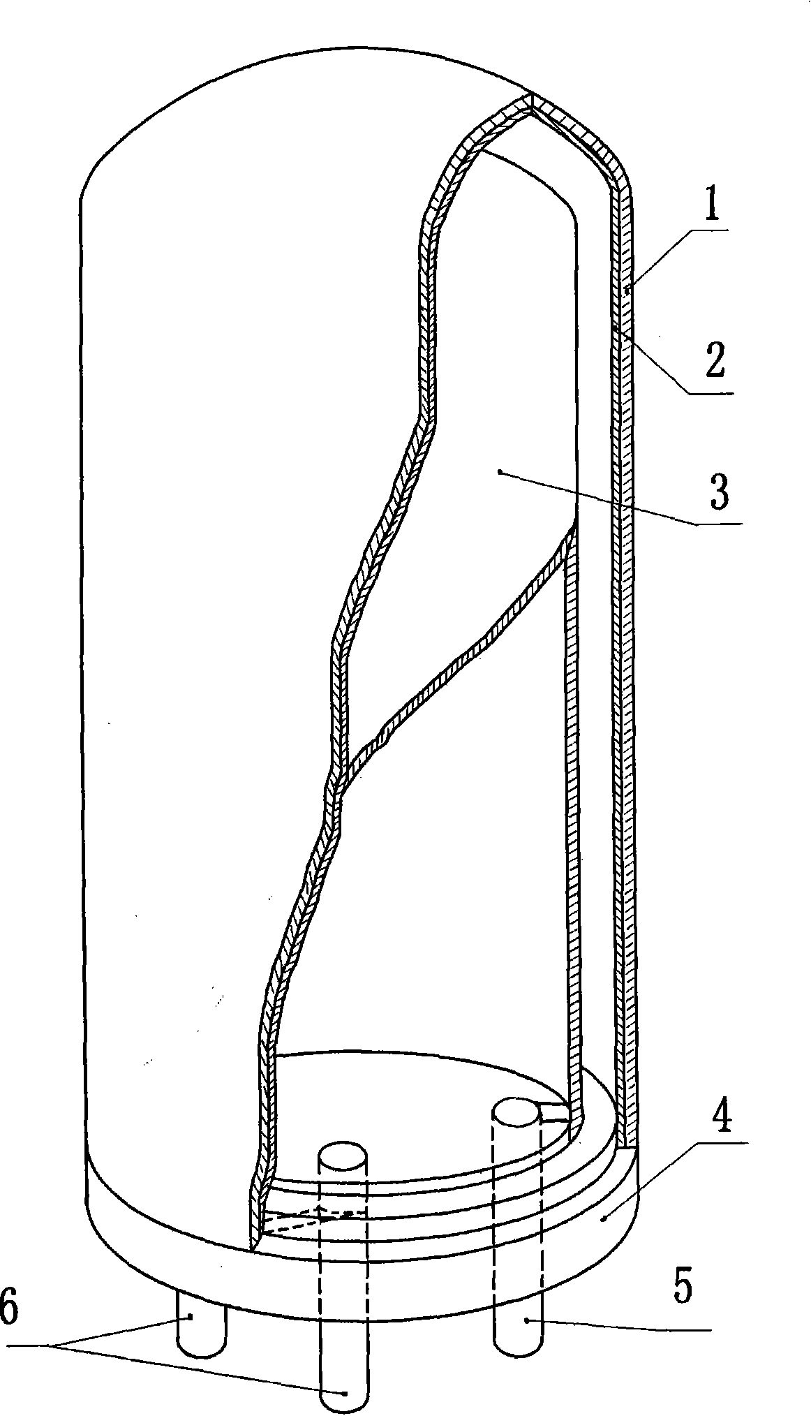
[0015] Take 10g of metallic sodium and place it on the tungsten wire heater of the vacuum coating machine, and put the vacuum glass tube mouth down on the coating frame. Then carry out a low vacuum in the bell jar of the coating machine, and the vacuum degree is ≥3×10 -3 mmHg. The vacuum chamber is then evacuated to high vacuum. At the same time, turn on the power supply of the heater, and the heater will heat the diffusion pump oil. The high vacuum time is 60 minutes. Vacuum degree is ≥5×10 - 6 mmHg. Start the tungsten wire heater to heat and vaporize metallic sodium or metallic cesium, and generate gaseous metal to attach to the inner wall of the glass tube to form a coating. The vaporization time is 4 minutes. Then block the tungsten wire heater baffle, and pressurize the tungsten wire heater to remove residual sodium or cesium on the heater. Then carry out high-vacuum treatment to make the coating film attached to the glass tube more firm, and the high-vacuum treatm...

Embodiment 2

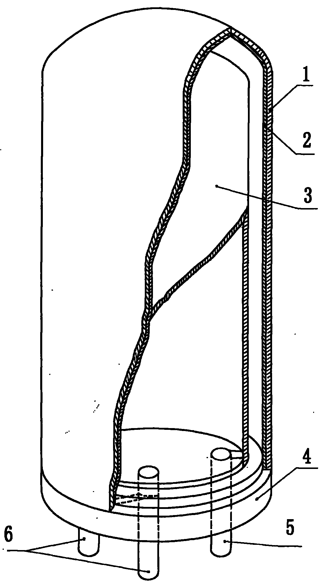
[0017] Get 15g of cesium metal and place it on the tungsten wire heater of the vacuum coating machine, and place the vacuum glass tube mouth down on the coating frame. Then carry out a low vacuum in the bell jar of the coating machine, and the vacuum degree is ≥3×10 -3 mmHg. The vacuum chamber is then evacuated to high vacuum. At the same time, turn on the power supply of the heater, and the heater will heat the diffusion pump oil. The high vacuum time is 60 minutes. Vacuum degree is ≥5×10 - 6 mmHg. Start the tungsten wire heater to heat and vaporize metallic sodium or metallic cesium, and generate gaseous metal to attach to the inner wall of the glass tube to form a coating. The vaporization time is 3 minutes. Then block the tungsten wire heater baffle, and pressurize the tungsten wire heater to remove residual sodium or cesium on the heater. Then carry out high-vacuum treatment to make the coating film attached to the glass tube more firm, and the high-vacuum treatmen...


PUM

PropertyMeasurementUnit
Thicknessaaaaaaaaaa

Abstract

The invention discloses a solar phototube and a manufacturing method thereof, and in particular relates to a solar phototube, i.e. a solar cell electrode and a manufacturing method thereof. The product is composed of a vacuum glass tube and a cylindrical aluminum foil. The manufacturing method thereof comprises the steps of: placing metallic sodium or cesium on a tungsten filament heater of a vacuum coating machine, putting the vacuum glass tube, with the mouth facing downwards, on a coating frame, performing sodium or cesium metallic film evaporation so that the inner wall of the vacuum glass tube is provided with a coating, and then assembling a plastic tube support, the cylindrical aluminum foil and the like. The phototube manufactured according to the method of the invention is based on the working principle that: when the sunlight irradiates the sodium metallic coating or the cesium metallic coating, electrons inside the coating escape immediately from the surface of the coating and form currents under the attraction of the anode of the aluminum foil so as to charge a storage battery. The solar phototube is provided with the vacuum glass tube the wall of which is provided with the sodium metallic coating or the cesium metallic coating, so a photoelectric conversion belt is in a tubular shape to reduce volume and floor space and enhance photoelectric conversion rate per unit area. Furthermore, owing to the adoption of sodium or cesium metal material, energy consumption is reduced, process is simplified and environmental pollution is lessened in the process of extraction and manufacturing. And a variety of problems of traditional products in terms of manufacturing method and use are settled.

Description

technical field [0001] The present invention relates to a method for the manufacture of solar photovoltaic cells, ie solar cells. Background technique [0002] At present, solar cells produced at home and abroad are manufactured using the principle of semiconductor PN junction photovoltaic effect, using silicon single wafers and gallium arsenide chips as photoelectric converters, and the photoelectric converters are matched with batteries to form solar power generation devices. Because the photoelectric converter of this power generation device is sheet-shaped, the photoelectric conversion rate per unit area is low. If the photoelectric conversion of a certain amount of electric energy is to be achieved, the volume of the photoelectric converter must be increased, so the device is large in size and heavy in weight. Large, the scope of use is limited. In addition, monocrystalline silicon wafers and gallium arsenide wafers have problems such as complex processes, many chemica...

Claims


Application Information

Patent Timeline
IPC IPC(8): H01L31/00H01L31/0216H01L31/02H01L31/18
CPCY02P70/50
Inventor 孟庆波王学礼
Owner 孟庆波
Why Eureka
Try Eureka