Design method for T-shaped microstrip electrode of novel polymer modulator
A technology of microstrip electrode and design method, which is applied in the field of optical communication to achieve the effect of improving the modulation bandwidth
Inactive Publication Date: 2011-06-15
UNIV OF ELECTRONICS SCI & TECH OF CHINA
View PDF0 Cites 5 Cited by
- Summary
- Abstract
- Description
- Claims
- Application Information
AI Technical Summary
Problems solved by technology
Of course, as far as the polymer material itself is concerned, the degree of speed mismatch is not as large as that of LiNbO3, but if a more perfect speed match can be achieved through device design, then the bandwidth will definitely be greatly improved. can reduce the conductor loss, then the modulator bandwidth will reach a new height
Method used
View moreImage
Smart ImageViewing Examples
Examples
Embodiment Construction
Login to View More PUM
| Property | Measurement | Unit |
|---|---|---|
| refractive index | aaaaa | aaaaa |
| refractive index | aaaaa | aaaaa |
| relative permittivity | aaaaa | aaaaa |
Abstract
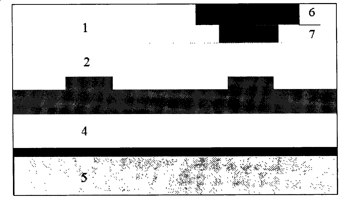
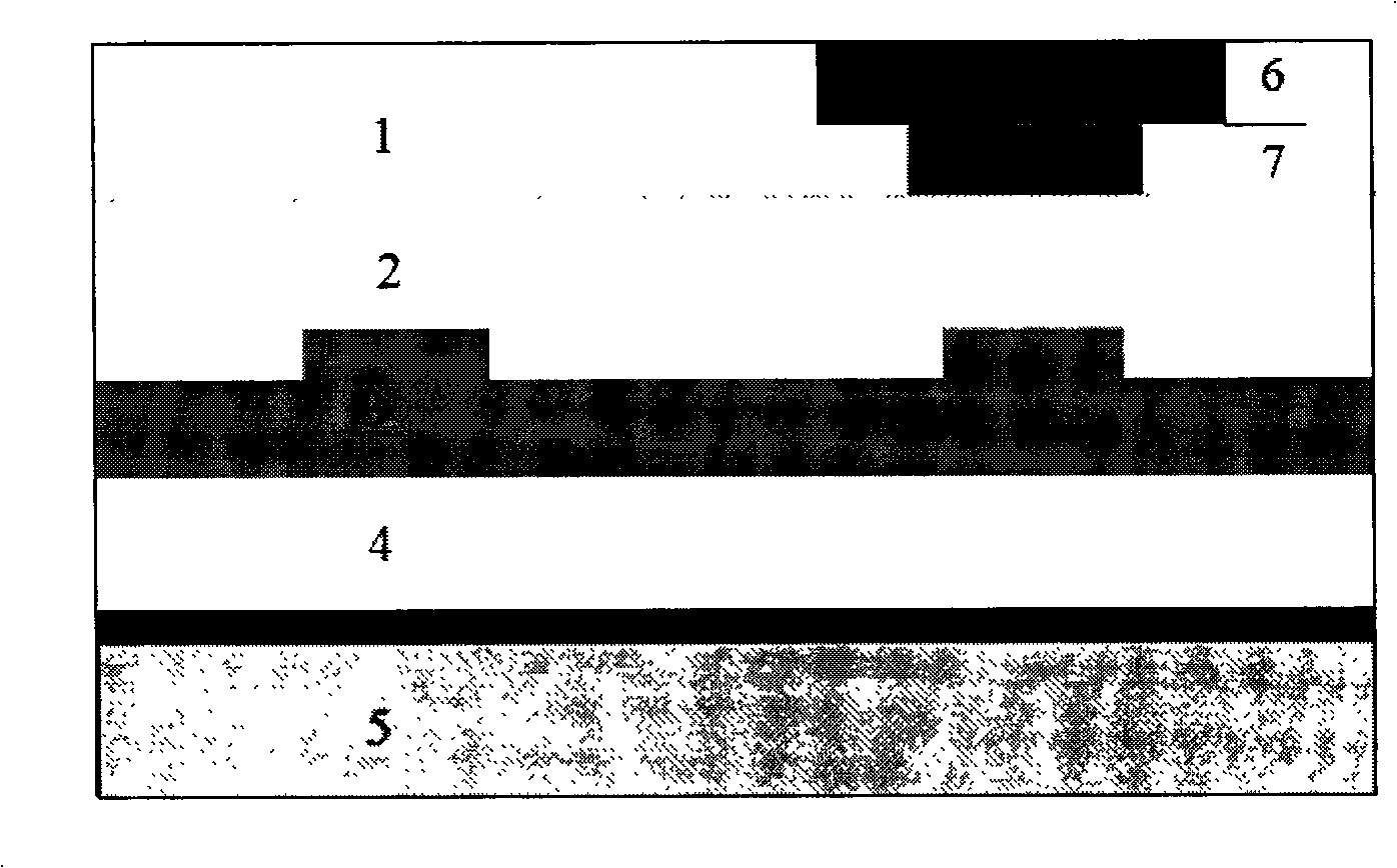
The invention provides a design method for a T-shaped microstrip electrode of a novel polymer modulator, belonging to the technical field of optical communication technology, relating to an optical waveguide technology and a microwave technology. The purpose of perfect speed matching can be carried out by means of appropriate electrode parameter design under the condition that the resistance is matched, and the band width of the modulator can be improved in a large degree. The invention provides an embedded type T-shaped microstrip electrode structure, wherein the microstrip of the structure increases the area on the edge of the electrode and reduces the singularity of the edge field, so that the consumption of the conductor is reduced. The design method for a T-shaped microstrip electrode of a novel polymer modulator provided by the invention has the advantages that the basically matched resistance can be obtained in a relatively wide range and the consumption of the conductor can be reduced by regulating the parameters of the structure factors of a microstrip line, and the band width of the modulator is improved.
Description
Design Method of T-shaped Microstrip Electrode for Novel Polymer Modulator technical field The design method of the T-type microstrip electrode of the new polymer modulator, the waveguide of the modulator adopts the polymer material, and the electrode adopts the microstrip line structure, which can realize the speed matching of light and microwave, belongs to the field of optical communication technology, and involves Optical waveguide technology and microwave technology. Background technique Compared with LiNbO3 modulators, polymer materials can provide better phase velocity matching between microwave and optical carriers, so polymer electro-optic modulators can generally achieve high modulation bandwidth. The current optical network system with a single channel transmission rate of 10Gbps and 40Gbps has been realized. Although the current polymer modulator and even the LiNbO3 modulator can meet this communication requirement in terms of modulation bandwidth, the future ...
Claims
Login to View More Application Information
Patent Timeline
 Patent Type & Authority Applications(China)
IPC IPC(8): H04B10/12G02B6/24G02F1/065
Inventor 张晓霞沈杰文玥刘宏明黄春阳朱燕
Owner UNIV OF ELECTRONICS SCI & TECH OF CHINA
- R&D Engineer
- R&D Manager
- IP Professional
- Industry Leading Data Capabilities
- Powerful AI technology
- Patent DNA Extraction
Learn More Browse by: Latest US Patents, China's latest patents, Technical Efficacy Thesaurus, Application Domain, Technology Topic, Popular Technical Reports.
© 2024 PatSnap. All rights reserved.Legal|Privacy policy|Modern Slavery Act Transparency Statement|Sitemap|About US| Contact US: help@patsnap.com


