Eureka AIR delivers breakthrough ideas for toughest innovation challenges, trusted by R&D personnel around the world.

Diaphragm pump diaphragm with combined sealing structure and diaphragm pump

A combined sealing and diaphragm pump technology, applied in the direction of pumps with flexible working elements, pumps, liquid variable capacity machines, etc., can solve the problems of reducing the performance of the diaphragm pump, water leakage, air leakage, damage to the diaphragm pump, etc., and achieve extended use. Longevity, avoidance of air leakage, and the effect of improving sealing ability

Active Publication Date: 2012-07-04
郑州绿帝农用机械有限公司
View PDF0 Cites 0 Cited by
  • Summary
  • Abstract
  • Description
  • Claims
  • Application Information

AI Technical Summary

Problems solved by technology

[0003] The sealing structure of the diaphragm of the existing diaphragm pump is simple, mainly relying on a sealing ring on its edge and the pressure of the pump body and the pump cover to realize the sealing of the diaphragm change. The sealing of the connection between the diaphragm and the valve seat is mainly The sealing is ensured by the pressure of the outer edge of the upper part of the valve seat on the diaphragm, and the sealing of the vibrating body part is mainly achieved by the buckling of the vibrating body sealing ring at the lower part of the diaphragm and the groove on the end face of the pump body to achieve sealing. Because the vibration of the diaphragm pump is relatively strong when it is running at high speed, it is easy to cause the above three parts to loosen, resulting in water leakage and air leakage, which will reduce the performance of the diaphragm pump, and what is more, damage the diaphragm pump.

Method used


Image

  • Diaphragm pump diaphragm with combined sealing structure and diaphragm pump
  • Diaphragm pump diaphragm with combined sealing structure and diaphragm pump
  • Diaphragm pump diaphragm with combined sealing structure and diaphragm pump

Examples


Embodiment 1

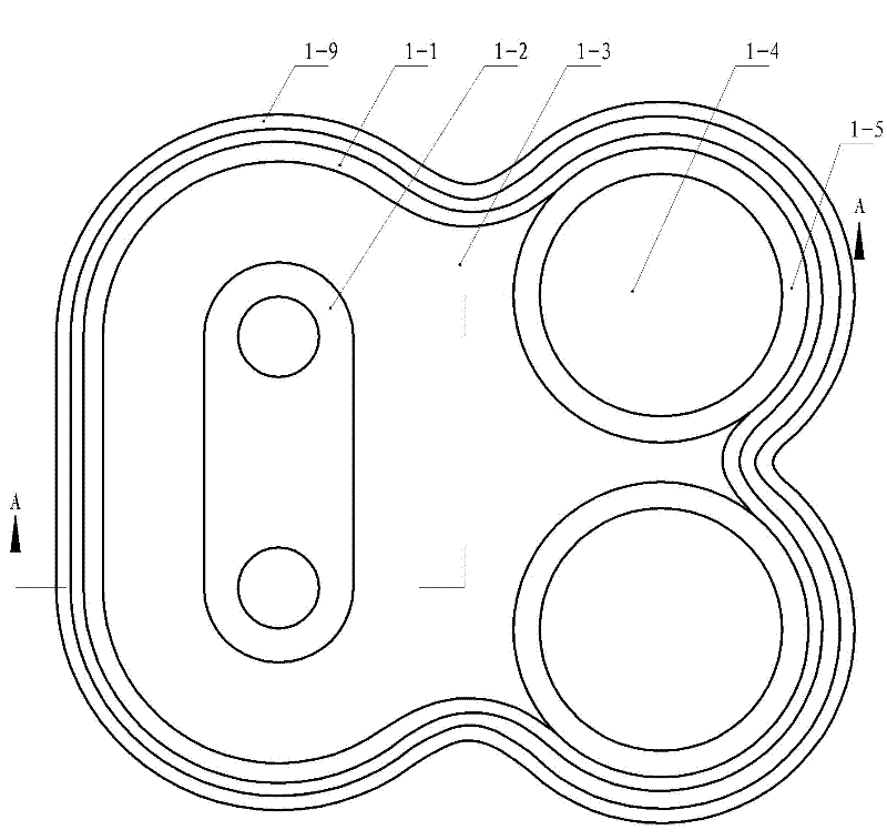
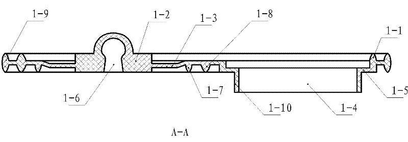
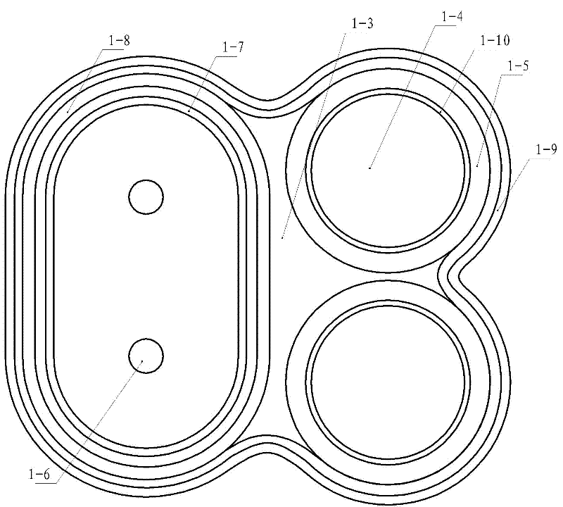
[0022] Embodiment one: see Figure 1-Figure 3 , a diaphragm pump diaphragm with a combined sealing structure in the figure. The diaphragm is formed as an integral diaphragm, including an outer sealing ring and an inner diaphragm body. The diaphragm body is provided with a vibration clamping part and a valve seat. In the installation hole, the vibration clamping part is provided with a vibrating body sealing ring, the vibrating body sealing ring is below the diaphragm, and the outer edge sealing ring is on the top of the diaphragm, and the outside of the outer edge sealing ring is also provided with An additional sealing ring on the outer edge matching the shape of the diaphragm, and the additional sealing ring on the outer edge is integrated with the outer sealing ring; The sealing ring of the vibrating body is similar in shape; the underside of the valve seat installation hole is provided with a protruding valve seat sealing sleeve.

[0023] The vibration clamping part is ar...

Embodiment 2

[0025] Embodiment two: see Figure 1-Figure 7 , a diaphragm pump with a combined sealing structure in the figure, including a pump body, a pump cover, a vibrating body, a diaphragm, and a valve seat; the valve seat and the vibrating device are installed in the pump body, and the diaphragm passes through the pump The cover is press-fitted on the end of the pump body; a volume-variable cavity is formed between the pump cover and the diaphragm as the pump chamber; the pump body is provided with two symmetrical valve chambers, and the two valve chambers are respectively connected to the The water inlet pipe on the pump body communicates with the water outlet pipe, and two valve seats are installed in each valve chamber; the diaphragm is integrally formed, including an outer sealing ring and an inner diaphragm body, on the diaphragm body There is a vibrating clamping part and a valve seat installation hole, the vibrating clamping part is provided with a vibrating body sealing ring,...


PUM


Abstract

The invention discloses a diaphragm pump diaphragm with a combined sealing structure and a diaphragm pump. The diaphragm comprises an outer edge sealing ring and an inner diaphragm body, wherein the diaphragm body is provided with a vibrating clamping part and a valve seat installation hole; the vibrating clamping part is provided with a vibrator sealing ring; the vibrator sealing ring is arranged below the diaphragm; the outer edge sealing ring is arranged above the diaphragm; an outer edge additional sealing ring of which the appearance is matched with that of the diaphragm is arranged outside the outer edge sealing ring; the outer edge additional sealing ring is connected with the outer edge sealing ring to form a whole body; an additional sealing ring is arranged inside the vibrator sealing ring; the shape of the sealing ring is similar to that of the vibrator sealing ring; a protruding valve seat sealing sleeve is arranged on the lower side of the valve seat installation hole; and the pump cover and the pump body of the diaphragm pump are provided with installation structures which are matched with the outer edge additional sealing ring, the vibrator additional sealing ring and the valve seat sealing sleeve. Through the improvement, the problem of the sealing of the diaphragm of the diaphragm pump is radically solved, the lift of the diaphragm pump is improved, the service life of the diaphragm pump is prolonged and unnecessary maintenance and waste is reduced.

Description

Technical field [0001] The invention relates to the technical field of diaphragm pumps for agricultural sprayers, in particular to a diaphragm pump diaphragm with a combined sealing structure and the diaphragm pump thereof. Background technique [0002] The sprayer is a small machine widely used in agriculture and forestry, and the common ones are manual and electric. The low-voltage electric sprayer is a replacement product of the manual sprayer. It uses dry batteries or batteries as the power source. The power source, pump body and liquid storage tank are installed together. The electric sprayer can greatly reduce the labor intensity of the operator, and the spray effect is good. It is a small sprayer that is currently used more. The core component of the electric sprayer is the pump, its structural performance and service life directly affect the performance and service life of the sprayer. [0003] The sealing structure of the diaphragm of the existing diaphragm pump i...

Claims


Application Information

Patent Timeline
Patent Type & Authority Patents(China)
IPC IPC(8): F04B43/02
Inventor 贾念国
Owner 郑州绿帝农用机械有限公司
Why Eureka
Eureka Blog
Learn More