
Automatic assembly method and assembly system for strain gauge

An automatic assembly, strain gauge technology, applied in metal processing, manipulators, metal processing equipment and other directions, can solve the problem of not considering whether the strain gauge will deflect, drift, whether the size is consistent, etc., to achieve good assembly accuracy, The effect of improving accuracy and consistency, and improving assembly accuracy

Inactive Publication Date: 2011-06-08
NINGBO UNIVERSITY OF TECHNOLOGY +1
View PDF6 Cites 27 Cited by
  • Summary
  • Abstract
  • Description
  • Claims
  • Application Information

AI Technical Summary

Problems solved by technology

As mentioned above, the positioning of the strain gauge box and the elastic body in the strain gauge automatic assembly system is realized through the positioning device on the platform, without considering whether the strain gauge will deflect or drift during the process of sucking the strain gauge by the air suction and discharge system and other factors, and does not consider whether the size of the elastic body is consistent during processing, which will bring unpredictable results to the accuracy and consistency of the assembly

Method used


Image

  • Automatic assembly method and assembly system for strain gauge
  • Automatic assembly method and assembly system for strain gauge
  • Automatic assembly method and assembly system for strain gauge

Examples


Embodiment

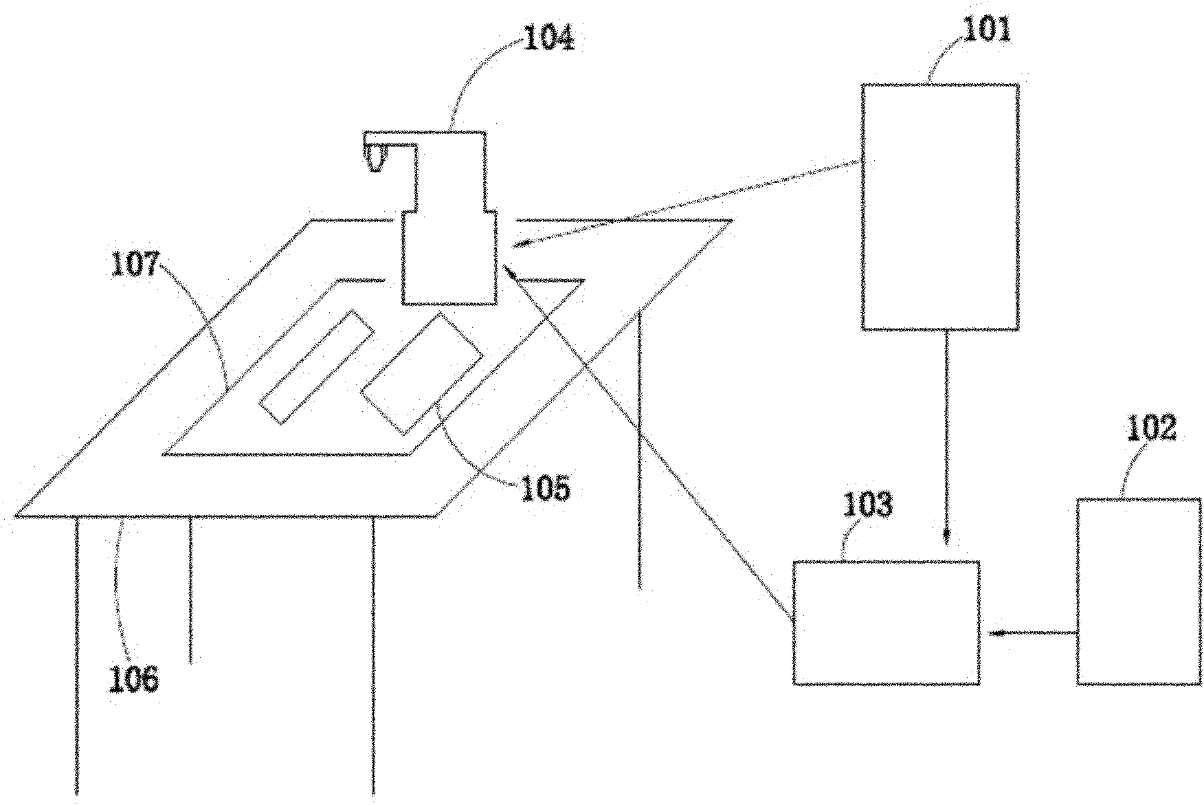
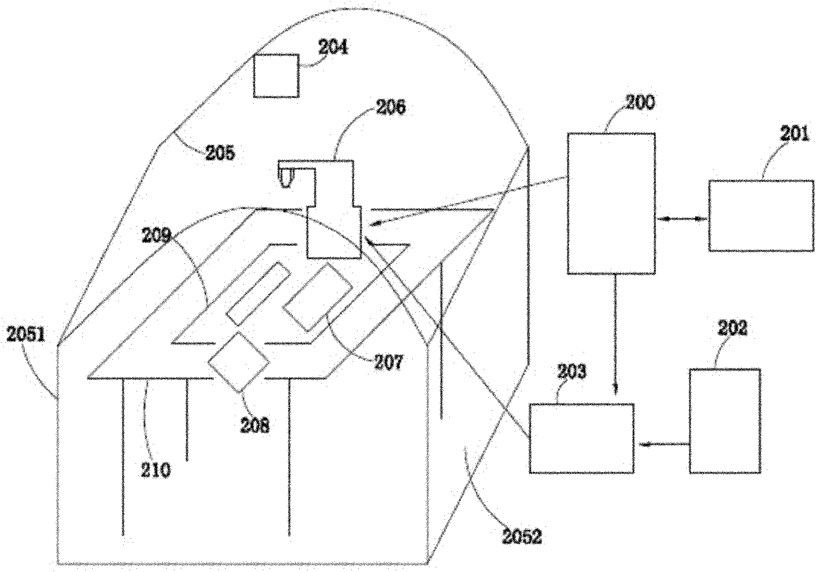
[0030] Such as figure 2 , Figure 7As shown, the method for automatic assembly of strain gauges provided in this embodiment includes the use of industrial computer 201 to control the mechanical arm 206 to automatically assemble the strain gauges. The precise positioning of the suction and placement of the strain gauges is to use the centering camera 208 and the bottom-finding camera 204 to collect images of the suction and placement positions of the strain gauges, and calculate the central position of the strain gauges through the image information of the centering camera 208, Deflection angle and offset; at the same time, according to the elastic body 209 image information provided by the bottom-finding camera 204 to place the strain gauge, calculate the elastic body 209 model, direction and center position of the assembly hole; after obtaining these information, pass the information through the communication channel Transmission to the robotic arm control cabinet 200, the ...


PUM


Abstract

The invention discloses an automatic assembly method and assembly system for a strain gauge. The method comprises the following steps: automatically assembling a corresponding strain gauge with a control mechanical arm of an industrial personal computer; performing image acquisition on the suction position and placing position of the strain gauge by use of a centering camera and a bottom searching camera; calculating the central position, deflection angle and offset of the strain gauge according to the image information in the centering camera; meanwhile, calculating the type and direction of an elastic body and the central position of an assembly hole according to the image information of the elastic body for placing the strain gauge provided by the bottom searching camera; and after obtaining the information, transmitting the information to a mechanical arm control cabinet through a communication channel, wherein the mechanical arm control cabinet obtains a motion path of the mechanical arm according to the information, controls the motion track of the mechanical arm, and controls an air suction / placing controller to perform corresponding suction and placing operations. According to the invention, better assembly precision, uniformity and reliability of the strain gauge are obtained, and influence of the service life of a position sensor on the system reliability is solved.

Description

technical field [0001] The invention relates to a technology for manufacturing a load cell, in particular to an automatic assembly method and assembly system for strain gauges. Background technique [0002] Usually, the strain gauge assembly system is used in manufacturing industries such as pressure sensors in the electronics industry. The strain gauge is the force sensitive element of the pressure sensor, which converts the physical force signal into an electrical signal. Therefore, in the production process of the pressure sensor, the strain gauge must be assembled to the force-sensitive position of the elastic body, and the position where the strain gauge is pasted has a decisive effect on the performance of the sensor. At present, the assembly of strain gauges is basically done manually in China, and only some industry giants in foreign countries have started to automatically assemble strain gauges in recent years. [0003] In the domestic manufacturing process of weig...

Claims


Application Information

Patent Timeline
Patent Type & Authority Applications(China)
IPC IPC(8): B23P19/00B25J9/16B25J19/00B25J15/06
Inventor 鲍吉龙郑德春何仲昆张永平傅越千林德法马形山许武川
Owner NINGBO UNIVERSITY OF TECHNOLOGY
Learn More