
Connection block

A junction box and interface technology, which is applied in the field of junction boxes, can solve the problems of conductor damage, joint force, conductor alignment difficulties, etc., and achieve the effect of reliable mechanical equipment

Active Publication Date: 2011-06-01
PHOENIX CONTACT GMBH & CO KG
View PDF4 Cites 10 Cited by
  • Summary
  • Abstract
  • Description
  • Claims
  • Application Information

AI Technical Summary

Problems solved by technology

If the module stack is longer and thus the number of conductors increases, the deflection of the conductors makes it more difficult to maintain correct conductor alignment during installation
Conductors may be damaged or joint forces may exceed permissible critical values

Method used


Image

  • Connection block
  • Connection block
  • Connection block

Examples


Embodiment Construction

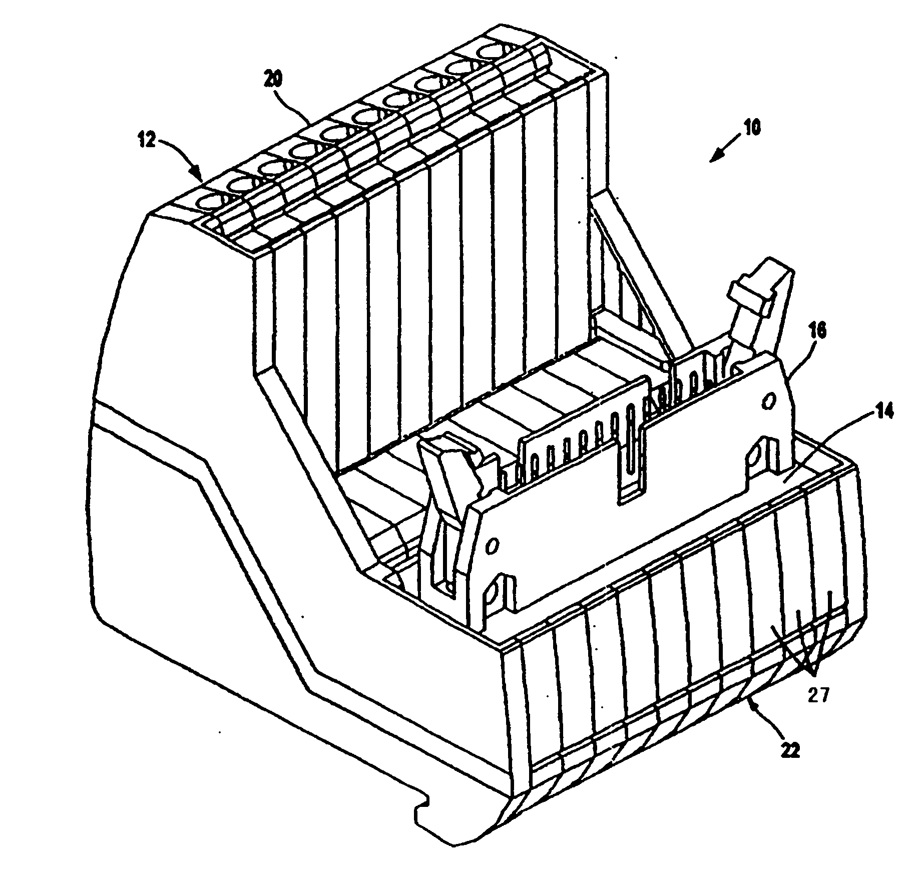
[0042] figure 1 and 2 A terminal box 10 according to the invention is shown. The junction box 10 includes a terminal box 12 and a printed circuit board 14 fixedly mounted on the terminal box 12 . A plurality of electrical conductors 44 extend from the terminal box 12 to rectangularly arranged through-contacts 168 in the circuit board 14, as described in detail below. These conductors electrically connect the terminals of the terminal box 12 and the circuit board 14 to each other.

[0043] The printed circuit board 14 is provided with a plug-in device 16 of the plug-in connector for receiving an electrical component to be connected to the junction box 10 . The plug device 16 is fixed on the circuit board 14, and besides the terminal box 12, a circuit board with other types of plug connectors may also be provided to connect the terminal box 10 with other types of electrical components.

[0044] The terminal box 10 is preferably designed for mounting on a conventional DIN rai...


PUM


Abstract

The present invention relates to a connection block for the electrical wiring and cabling of interfaces, having a modular terminal block (12) and a printed circuit board (14) mounted on the terminal block. The modules (27) form, by way of their module housings (28), a conductor housing (46) for a large number of conductors (44) which are separately conducted out of the conductor housing (46) in the form of conductor pins (74). The printed circuit board (14) has plug-through contacts (168) with which it is plugged onto the separate conductor pins (74). An orientation plate (158) with passage holes (164) is provided for positioning the conductor pins (74), and accordingly the conductors (74) are held in the conductor housing (46) such that they can firstly withstand the forces acting on them when the orientation plate (134) and the printed circuit board (14) are fitted, and secondly can yield for corrective orientation.

Description

technical field [0001] The invention relates to a junction box for electrical wiring and wire connection of interfaces. This generally refers to the connection of a multi-pin plug connector on the wiring of an electrical device. Background technique [0002] Such a junction box has a terminal box comprising a conductor housing with a plurality of terminals and a receiving area connected to the conductor housing on the side facing away from the terminals, the receiving area has a area on the circuit board. The multi-lead plug device of the plug connector is arranged on the circuit board, and the conductors connected to the terminals pass through the conductor housing, and the conductors are connected to the circuit board at the other end. The conductors protrude from the conductor housing and are arranged in such a way that they can come into engagement with the contacts of the printed circuit board. [0003] A modular junction box consists of a module stack consisting of ...

Claims


Application Information

Patent Timeline
IPC IPC(8): H01R13/02H01R9/24H01R13/514H01R13/66H01R12/58
CPCH01R9/2625H01R12/585H01R4/36H01R9/2616H01R13/514H01R9/093H01R12/515
Inventor M·A·科雷尔
Owner PHOENIX CONTACT GMBH & CO KG
Learn More