Eureka AIR delivers breakthrough ideas for toughest innovation challenges, trusted by R&D personnel around the world.

Fluidized bed gasifier with solids discharge and classification device

A fluidized bed reactor, solid particle technology, applied in chemical instruments and methods, mechanical details of gasification devices, feeding tools of gasification devices, etc., can solve problems such as combustion in wind chambers

Inactive Publication Date: 2011-06-01
SYNTHESIS ENERGY SYST
View PDF8 Cites 10 Cited by
  • Summary
  • Abstract
  • Description
  • Claims
  • Application Information

AI Technical Summary

Problems solved by technology

However, solid particles in the fluidized bed usually flow through the openings of the distribution plate and fall into the plenum below the distribution plate, causing adverse problems such as plenum combustion

Method used


Image

  • Fluidized bed gasifier with solids discharge and classification device
  • Fluidized bed gasifier with solids discharge and classification device
  • Fluidized bed gasifier with solids discharge and classification device

Examples


Embodiment Construction

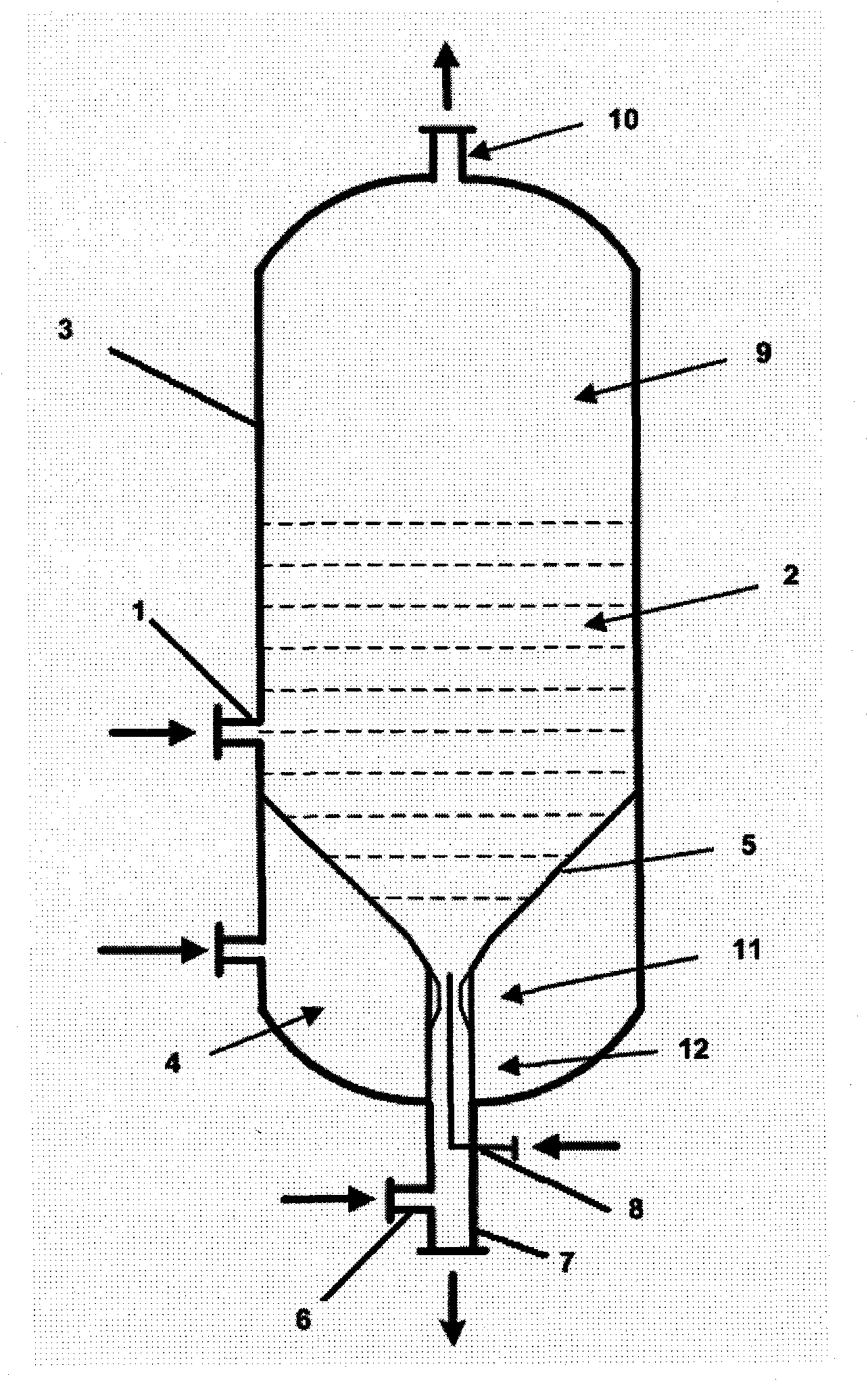
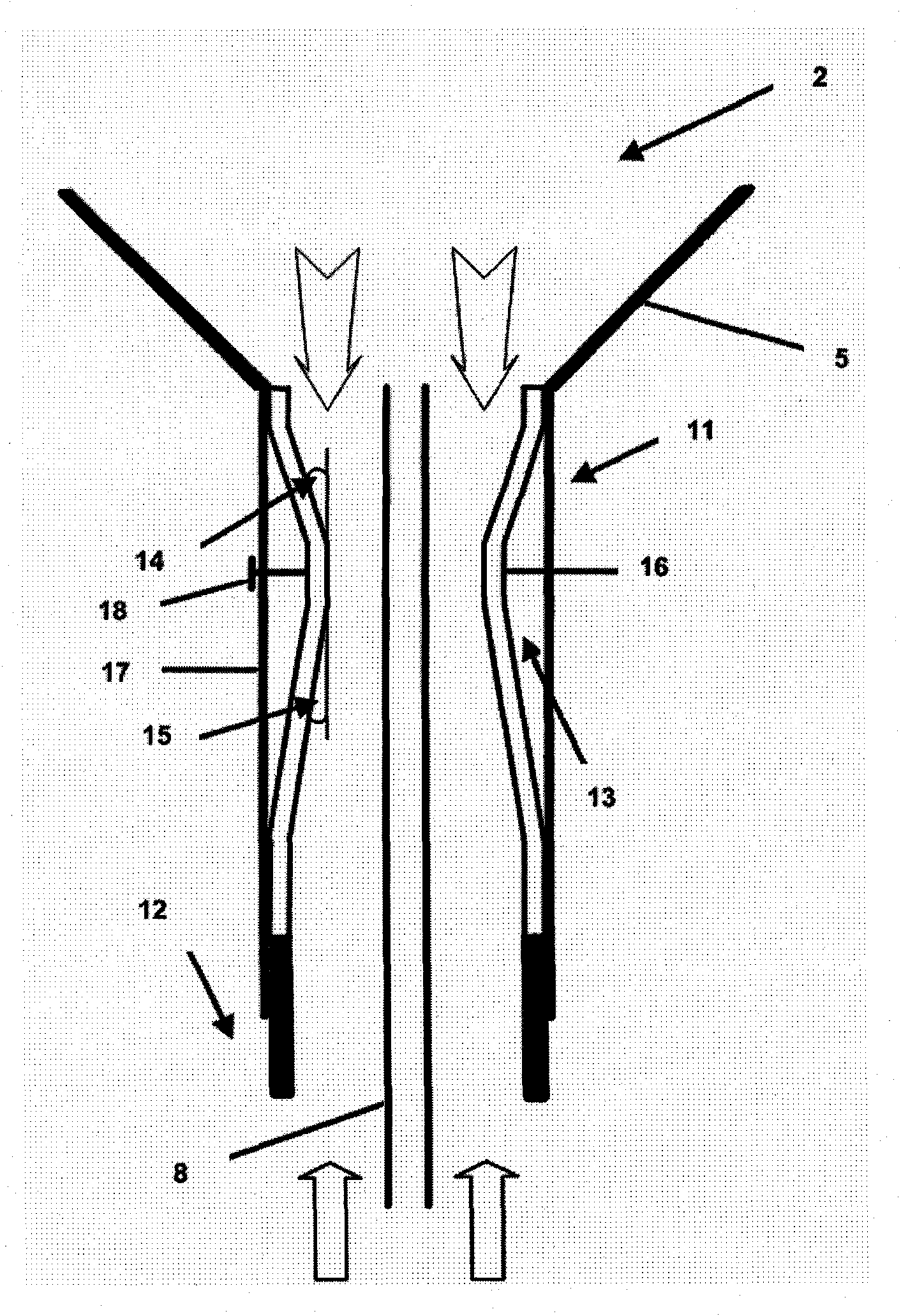
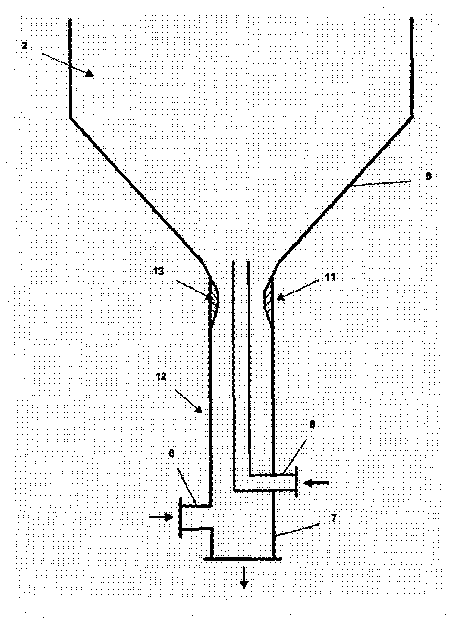
[0021] As shown in the figure, various aspects of the present invention will be described in more detail below. figure 1 A schematic diagram of an embodiment of the fluidized bed gasifier of the present invention is provided. The fluidized bed gasifier includes a solid particle residue discharge and classification integrated device. The solid particulate raw material includes crushed carbonaceous fuel such as coal or biomass, and is fed to the fluidized bed 2 of the gasifier 3 pneumatically or mechanically through the feeding pipe 1. The gas-phase raw materials containing water vapor and an oxidant mixture gas such as air or oxygen enter the vaporizer 3 from the following three locations: 1) "Grid gas" enters from the wind chamber 4 located below the diffusion grid 5, 2) The "classified gas" enters from the ash discharge pipeline 7 through the connecting pipe 6, and 3) the "jet gas" enters from the central jet pipe 8.

[0022] The solid particle raw material is controlled to che...


PUM


Abstract

The present invention provides an apparatus for withdrawing solids from a fluidized bed reactor, comprising a venturi tube connected to the stem end of a funnel-shaped distribution plate, and a center jet pipe enclosed within the venturi, wherein a jet stream of feed gas is delivered above the venturi throat. Preferably, the distribution plate is equipped with multiple horizontally- or downwardly- oriented grid holes through which the feed gases flow and enter the fluidized bed, which holes may be covered by metal plates to prevent solids from weeping through grid holes and falling into the plenum below the distribution plate. The venturi is preferably engineered to be readily removable from the rest of the gasifier reactor for repair or replacement. Also provided is a fluidized bed reactor comprising the above apparatus.

Description

Technical field [0001] The invention relates to a device for diffusing raw material gas into a fluidized bed reactor and discharging solid particle residues out of the fluidized bed reactor. Background technique [0002] The solid particle residue produced by the fluidized bed reactor operating at high temperature and high pressure needs to be discharged out of the gasifier in a controlled and stable manner to maintain sufficient bed height and solid particle residence time required for the gasification reaction. The traditional fluidized bed gasifier underflow discharge system works at high temperature and high pressure and uses control valves and mechanical feeders, which often causes irregular solid particle flow rates and severely high impact on the mechanical part of the discharge device. Corrosion wear. The mechanical design, construction and operation of control valves and mechanical feeders are very complicated and require frequent maintenance and replacement. Tradition...

Claims


Application Information

Patent Timeline
Patent Type & Authority Applications(China)
IPC IPC(8): B01J8/00B01J8/18
CPCC10J2300/0916C10J2300/093B01J8/003C10J3/523B01J8/44B01J2208/00778C10J2200/09B01J2208/00761B01J8/1818C10J2300/0956Y02E20/18C10J2200/15C10J2300/0973
Inventor 宗耀·罗伯特·盛
Owner SYNTHESIS ENERGY SYST
Why Eureka
Eureka Blog
Learn More