
Hydraulic supporting, leveling and clamping device of large-size working piece

A clamping device, a technology for large workpieces, applied in the direction of manufacturing tools, metal processing equipment, grinding machine parts, etc., can solve the problems of unusable production lines, high equipment cost, complex and huge structure, etc., to improve production efficiency and save money. The effect of equipment cost

Active Publication Date: 2013-07-31
浙江杭机股份有限公司
View PDF0 Cites 0 Cited by
  • Summary
  • Abstract
  • Description
  • Claims
  • Application Information

AI Technical Summary

Problems solved by technology

In this way, the structure of the machine tool equipment is complex and huge, the drive system needs a large power source, the equipment cost is high, and it is very uneconomical, so the existing machine tool equipment lacks a moving device for installing large and heavy-duty workpieces
Even if there is a floor-standing machine tool in which the workpiece is fixed and fixed, a floor-standing workbench is required to install the workpiece, and a corresponding site foundation is required. The workpiece needs to be manually corrected and leveled, which is time-consuming and laborious
Another important situation is that neither of these two forms can be used in the production line, and it is not suitable for assembly line automation.

Method used


Image

  • Hydraulic supporting, leveling and clamping device of large-size working piece
  • Hydraulic supporting, leveling and clamping device of large-size working piece
  • Hydraulic supporting, leveling and clamping device of large-size working piece

Examples


Embodiment 1

[0032] The processing object is the CRTS Ⅱ Borg ballastless track slab used in the construction of high-speed railway with a speed of 350 kilometers per hour. Workpiece appearance length × width × height dimensions: 6450 × 2550 × 200 (mm), weighing 9 tons. The material is special concrete.

[0033] The invention can also be used for supporting, leveling and clamping installation of other large heavy-duty boards and box-type components.

[0034] The working process and principle of workpiece 10 movement, leveling and clamping:

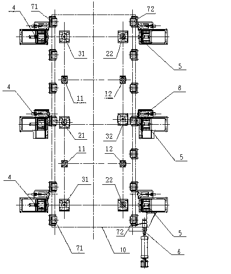
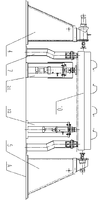
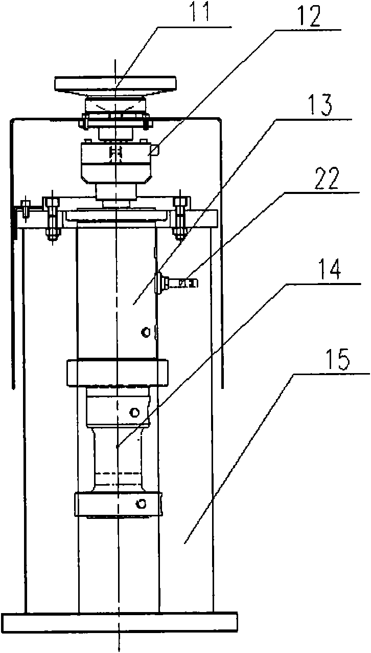
[0035] Such as figure 1 , 2 , 3, and 4, the workpiece 10 is sent to the processing position from the previous station by the transmission support roller assembly one, two 7-1, 7-2 through the guide of the roller guide mechanism 8, and the longitudinal positioning mechanism 6 pairs the workpiece 10 for vertical orientation. Under the control of the control system, the three jacking cylinder assemblies 1, 2 2-1, 2-2 and the three pressure regulating ...


PUM


Abstract

The invention relates to a hydraulic supporting, leveling and clamping device of a large-size working piece, comprising supporting oil cylinder components, a jacking oil cylinder component, a pressure-regulating oil cylinder component, positioning oil cylinder components, clamping oil cylinder components, a longitudinal positioning mechanism, a conveying supporting roller component, a roller guiding mechanism, a control system, and the like. The jacking oil cylinder component and the pressure-regulating oil cylinder component are mounted on a base plane A at the same heights, mutually crossedand distributed in parallel in three points forming an isosceles triangle, the plurality of supporting oil cylinder components are arranged on the base plane A at the same heights and coaxially and uniformly distributed between the jacking oil cylinder component and the pressure-regulating oil cylinder component at the same height; and the plurality of positioning oil cylinder components and the plurality of clamping oil cylinder components are respectively arranged at the left and the right of the jacking oil cylinder component and the pressure-regulating oil cylinder component and uniformlydistributed at the same heights. The invention has the advantages of saving equipment cost and being good for energy saving and emission reducing, is suitable for automatic operation on a production line, can automatically level and clamp a working piece and improve the production efficiency.

Description

technical field [0001] The invention relates to a machining device, in particular to a large workpiece hydraulically supported leveling and clamping device. Background technique [0002] The cutting machine tool workpieces of mechanical processing equipment are mostly installed on the workbench for processing. For large and heavy-duty workpieces installed on the workbench, the machine tool equipment requires a large drag device and driving force. The structure of the machine tool equipment is complex and huge like this, and the drive system needs a large power source, and the equipment cost is high, which is very uneconomical. Therefore, the existing machine tool equipment lacks a movable device for installing large-scale heavy-duty workpieces. Even if there is a floor-standing machine tool in which the workpiece is fixed and fixed, a floor-standing workbench is required to install the workpiece, and a corresponding site foundation is required. The workpiece needs to be manu...

Claims


Application Information

Patent Timeline
Patent Type & Authority Patents(China)
IPC IPC(8): B24B41/00
Inventor 董凯夫黄春韶林晓吴强洪徐慧芳陈晓林达叶铁裘卓明
Owner 浙江杭机股份有限公司
Learn More