Method for thermally compensating gaging device and thermally compensated gaging station

A metering device and heat compensation technology, which is applied in the direction of transmitting sensing components, instruments, etc. by fluid devices, can solve the problems that compensation cannot be achieved, and known methods cannot be applied.

Inactive Publication Date: 2011-05-25
MARPOSS SPA
View PDF3 Cites 1 Cited by
  • Summary
  • Abstract
  • Description
  • Claims
  • Application Information

AI Technical Summary

Problems solved by technology

[0004] However, known methods (for example of the same type as described in patent US5689447A1) for determining the value of the thermal compensation coefficient involve rather significant estimates, so that these methods do not achieve a very accurate compensation
Therefore, the known method cannot be applied to metrology applications requiring extremely high precision

Method used


Image

  • Method for thermally compensating gaging device and thermally compensated gaging station
  • Method for thermally compensating gaging device and thermally compensated gaging station
  • Method for thermally compensating gaging device and thermally compensated gaging station

Examples


Embodiment Construction

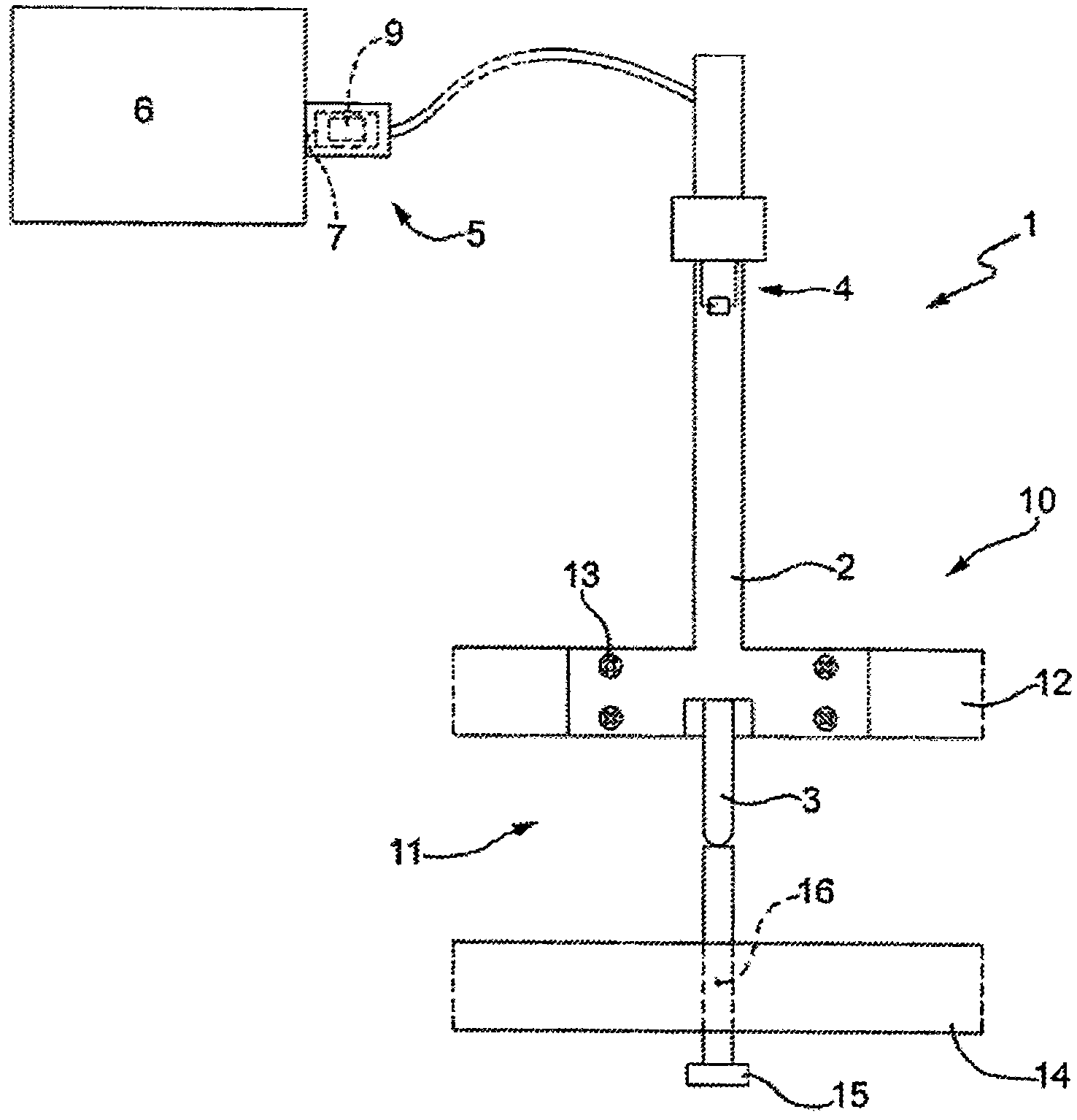
[0012] in figure 1 Here, the reference sign 1 generally indicates a metering device, such as a position sensor including a linear transducer of the LVDT (Linear Variable Differential Transformer) type, such as the same type as the position sensor described in US Pat. No. 6,931,749 B1. The metering device or position sensor 1 includes a fixed part 2 and a movable element, and the movable element is more specifically a slider 3 with a contact and movable relative to the fixed part. The transducer of the position sensor 1 includes a winding and a movable iron core (which are known per se and are therefore not shown in the drawings) respectively connected to the fixed part 2 and to the movable element or slider 3, and is suitable for providing An alternating current signal, which has a variable intensity voltage and depends on the position of the movable slide 3. The winding of the transducer of position sensor 1 is figure 1 The part of the circuit schematically indicated by refere...


PUM


Abstract

Thermal drifts compensation method in a gaging device (1) with a transducer; the compensation method includes the steps of : determining and storing, in the course of a calibration operation, values of a thermal compensation coefficient (K) upon variation of a temperature (T) of the gaging device (1); detecting, in the course of a gaging operation, a current reading (X) of the gaging device (1); detecting, in the course of the gaging operation, a current temperature (T) of the gaging device (1); determining, in the course of the gaging operation, the current value of the thermal compensation coefficient (K) by means of the values of the thermal compensation coefficient (K) previously determined and stored in the course of the calibration operation as a function of both the current temperature (T) of the gaging device (1) and the current reading (X) of the gaging device (1); and correcting, in the course of the gaging operation, the current reading (X) of the gaging device (1) by meansof the current value of the thermal compensation coefficient (K).

Description

Technical field [0001] The invention relates to a method for thermally compensating a metering device, and a metering station to be thermally compensated. Background technique [0002] Because temperature changes cause so-called thermal drift, which is caused by the inevitable thermal deformation of the metal component part of the position sensor and the inevitable change in the circuit resistance of the position sensor, so among other things, the ambient temperature will affect Information provided by the metering device of the position sensor. In an attempt to provide a sensor that is less affected by temperature changes, a position sensor can be implemented with a metal with limited thermal deformation and limited resistance change. However, a metering device that is completely unaffected by temperature changes cannot be obtained. [0003] In high-precision metering devices and sensors, it is known to perform compensation of the reading provided by the sensor based on the ambi...

Claims


Application Information

Patent Timeline
Patent Type & Authority Applications(China)
IPC IPC(8): G01D5/42
CPCG01D5/42G01D18/00
Inventor B·萨内特M·阿尔德罗万迪W·蒙塔纳里
Owner MARPOSS SPA
Why Eureka
Try Eureka