Magnetic gear shifting mechanism

A speed change mechanism and magnetic gear technology, which is applied to belts/chains/gears, mechanical equipment, transmission devices, etc., can solve problems such as lack of mature technical solutions and complex mechanisms, and achieve the effect of simple structure and low energy consumption

Inactive Publication Date: 2011-05-25
靳北彪
View PDF0 Cites 3 Cited by
  • Summary
  • Abstract
  • Description
  • Claims
  • Application Information

AI Technical Summary

Problems solved by technology

[0002] Although the mechanical gear transmission mechanism is reliable, the mechanism is complex. In recent years, the research and development of using magnetic gears for transmission is increasing, but there are almost no mature technical solutions.

Method used


Image

  • Magnetic gear shifting mechanism
  • Magnetic gear shifting mechanism
  • Magnetic gear shifting mechanism

Examples


Embodiment 1

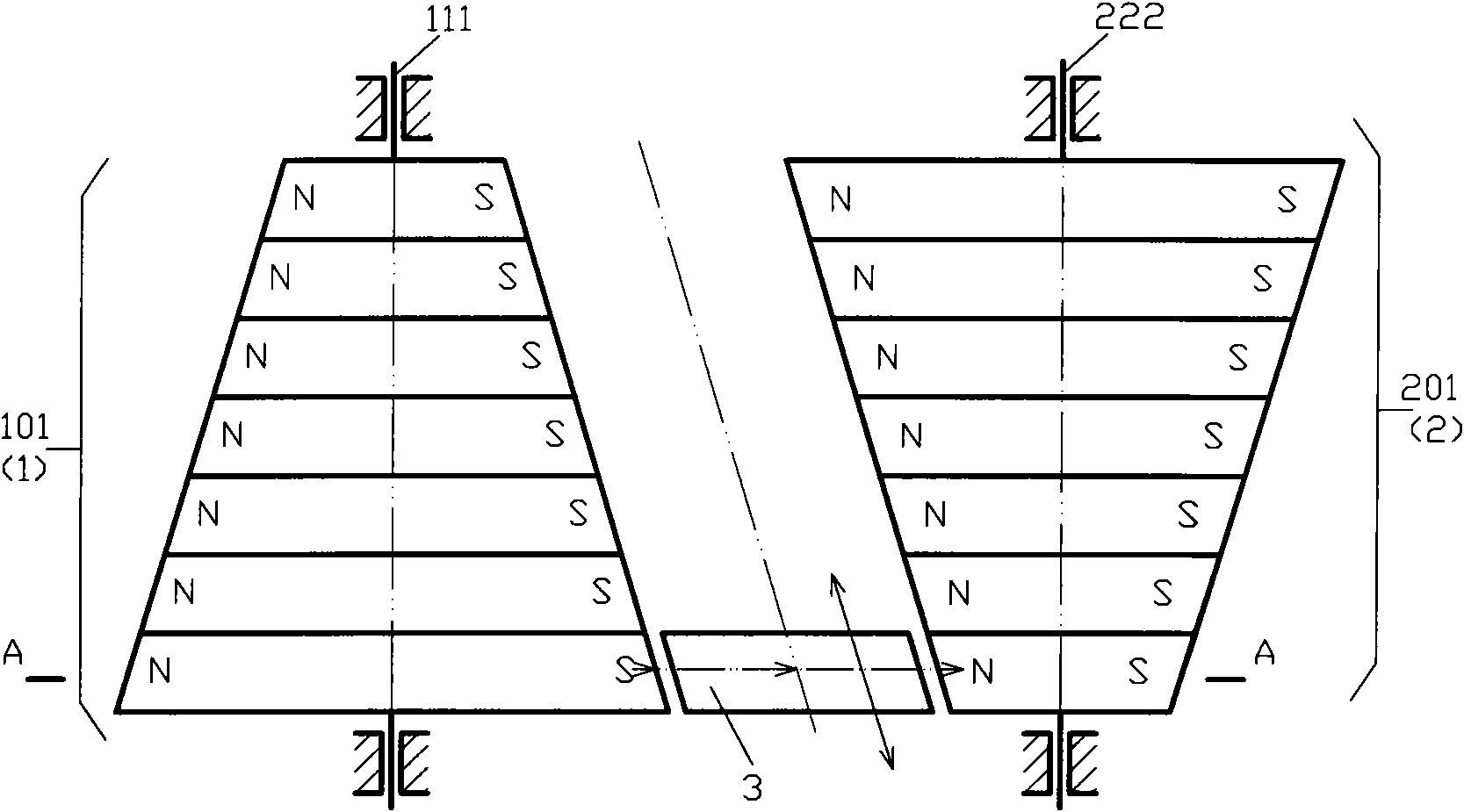
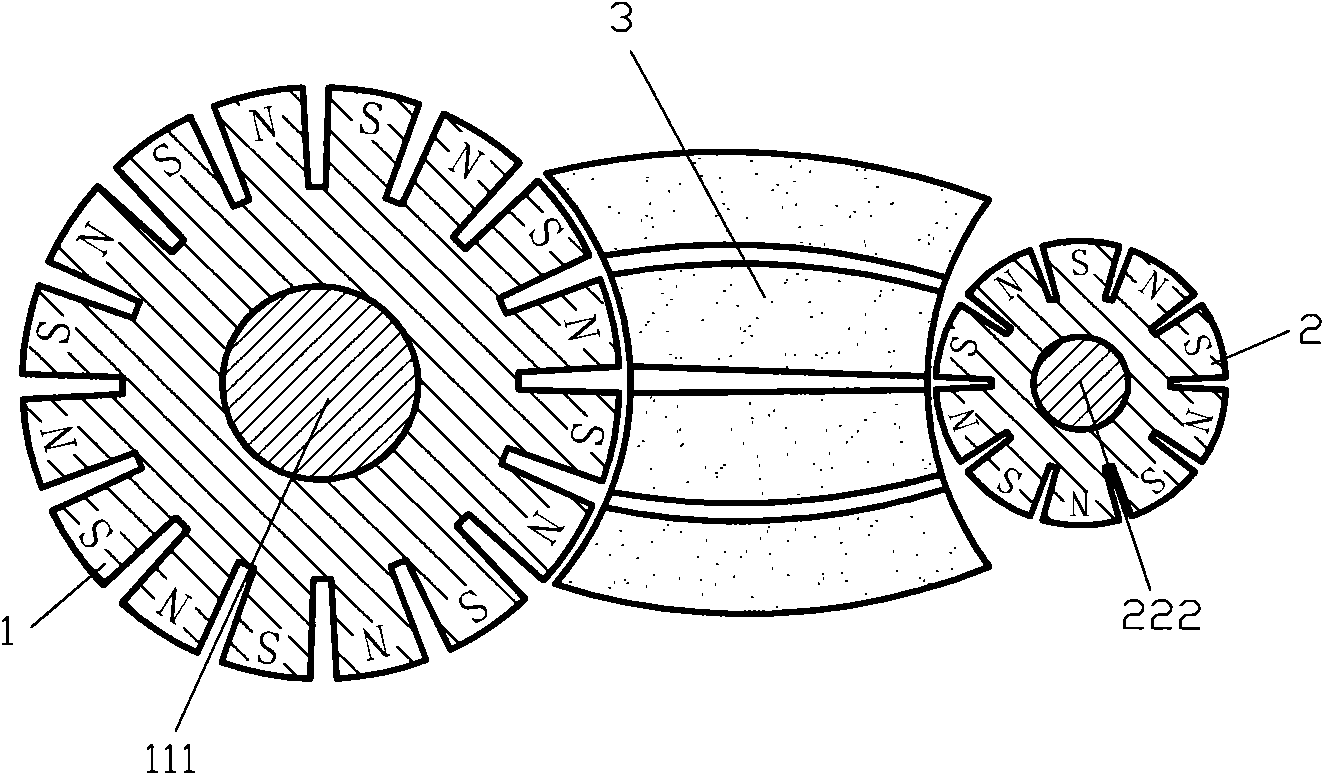
[0033] Such as figure 1 and figure 2 The shown magnetic gear speed change mechanism includes a first magnetic gear set 1 and a second magnetic gear set 2. The first magnetic gear set 1 is set to be composed of N magnetic gears coaxially arranged, and the second magnetic gear set 2 is set to consist of M magnetic gears are coaxially arranged, and the sum of M plus N is greater than or equal to 3; the diameters of the magnetic gears in the first magnetic gear set 1 are set to be the same, and the diameters of the magnetic gears in the second magnetic gear set 2 are set to be different, Or the diameters of the magnetic gears in the second magnetic gear set 2 are set to be the same, the diameters of the magnetic gears in the first magnetic gear set 1 are set to be different, or the diameters of the magnetic gears in the first magnetic gear set 1 are set to be different, The diameter of the magnetic gear in the second magnetic gear set 2 is set to be different; Between the first ...

Embodiment 2

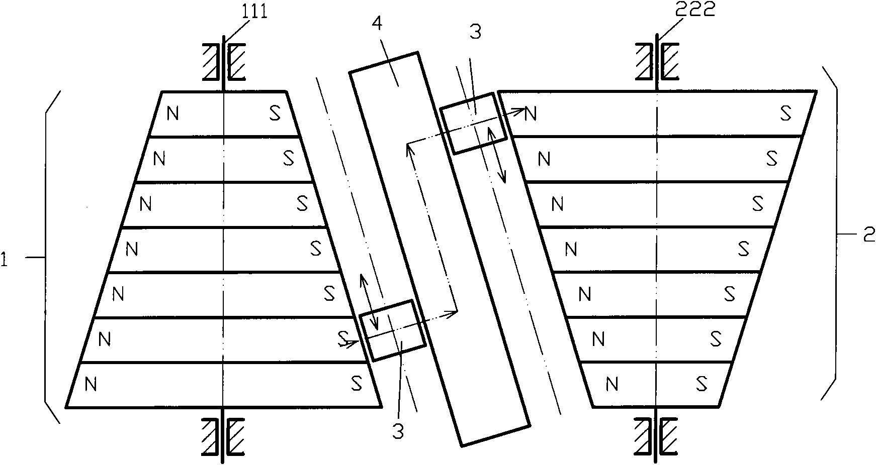
[0035] Such as image 3 The difference between the shown magnetic gear transmission mechanism and Embodiment 1 is that two moving magnetizers 3 are arranged in series between the first magnetic gear set 1 and the second magnetic gear set 2, and between the two moving magnetizers 3 There are fixed magnetizers 4 between them.

Embodiment 3

[0037] Such as Figure 4 The difference between the shown magnetic gear transmission mechanism and Embodiment 2 is that a first shape-compensating fixed magnetizer 401 is set between the first magnetic gear set 1 and the moving magnetizer 3, and a fixed magnetizer 401 is set between the moving magnetizer 3 and the second magnetizer. A second shape-compensating fixed magnetic conductor 402 is arranged between the gear sets 2 . Shape Compensation The fixed magnetic conductor has two functions: one is to compensate the shape change caused by the change of the radius of curvature of the magnetic gear, and the other is to enable the mobile magnetic conductor to maintain a relatively large and stable magnetic pole corresponding surface during the moving process to ensure sufficient torque and shape. The compensation fixed magnetizer should run through the entire length of the magnetic gear set.


PUM


Abstract

The invention discloses a magnetic gear shifting mechanism which comprises a first magnetic gear set and a second magnetic gear set. The first magnetic gear set comprises N magnetic gears coaxially arranged, the second magnetic gear set comprises M magnetic gears coaxially arranged, and the sum of M and N is greater than or equal to 3; the diameters of the magnetic gears in the first magnetic gear set are equal, and the diameters of the magnetic gears in the magnetic gear set are different; and at least one moving magnetizer is arranged between the first magnetic gear set and the second magnetic gear set, and transfers the magnetic lines of force of certain magnetic gear of the first magnetic gear set to certain magnetic gear of the second magnetic gear set, and either of a shaft A of the first magnetic gear set and a shaft B of the magnetic gear set is set as a power input shaft, and the other one is set as a power output shaft. The magnetic gear shifting mechanism disclosed by the invention has the advantages of simple structure and low energy consumption, and does not need lubrication.

Description

technical field [0001] The invention relates to the field of thermal energy and power, in particular to a magnetic gear transmission mechanism. Background technique [0002] Although the mechanical gear transmission mechanism is reliable, the mechanism is complex. In recent years, the research and development of using magnetic gears for transmission is increasing, but there are almost no mature technical solutions. The magnetic gear transmission mechanism has the advantages of simple structure, low energy consumption, and no need for lubrication. In order to improve the transmission efficiency of the engine and other mechanical fields, it is urgent to invent a magnetic gear transmission mechanism with reliable performance. Contents of the invention [0003] In order to solve the above problems, the technical scheme proposed by the present invention is as follows: [0004] A magnetic gear speed change mechanism, comprising a first magnetic gear set and a second magnetic ge...

Claims


Application Information

Patent Timeline
Patent Type & Authority Applications(China)
IPC IPC(8): F16H49/00
Inventor 靳北彪
Owner 靳北彪
Why Eureka
Try Eureka