
Headlamp

A technology of headlights and shells, which is applied in the field of headlights and can solve the problems of consumption and high cost

Inactive Publication Date: 2014-11-19
海拉有限双合股份公司
View PDF8 Cites 0 Cited by
  • Summary
  • Abstract
  • Description
  • Claims
  • Application Information

AI Technical Summary

Problems solved by technology

However, such a solution is costly and expensive

Method used


Image

  • Headlamp
  • Headlamp
  • Headlamp

Examples


Embodiment Construction

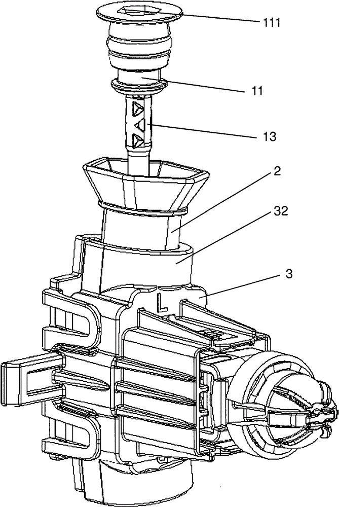
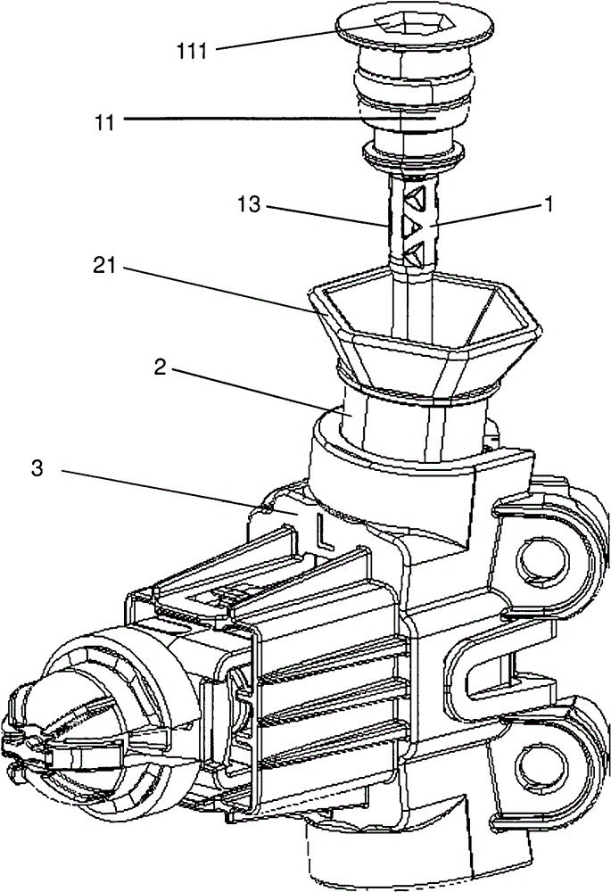
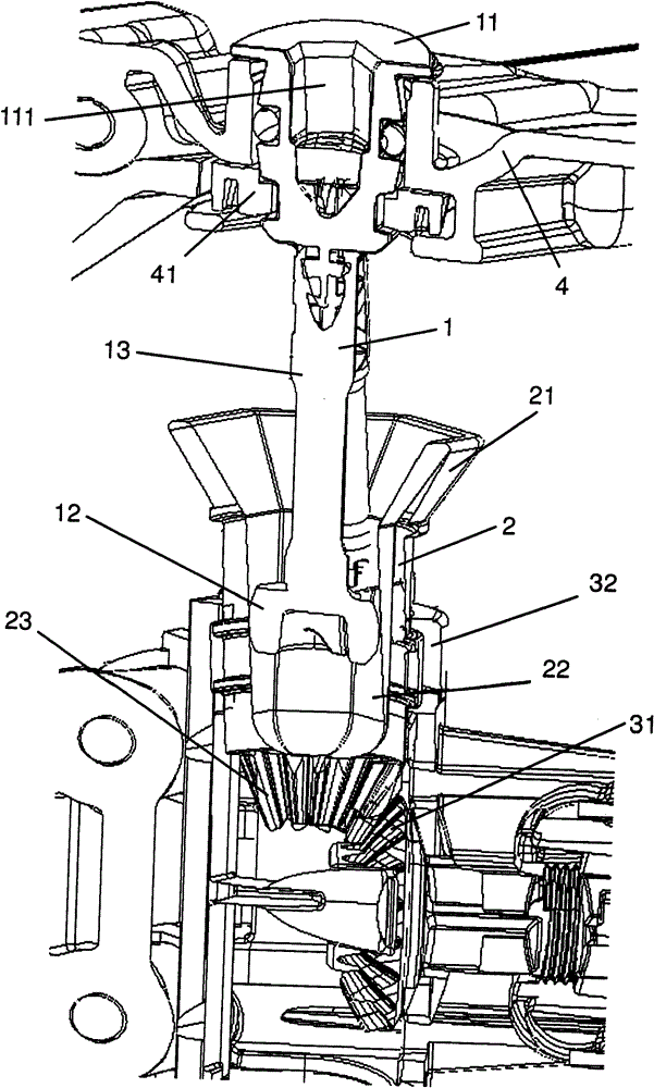
[0027] According to the headlamp of the present invention, in figure 1 and 2 The part shown from different sides comprises drive shafts 1 , 2 and a transmission 3 which can be driven via the drive shaft.

[0028] The drive shaft 1 , 2 has two shaft parts, namely a first shaft part 1 and a second shaft part 2 . The two shaft parts 1, 2 are splined to each other, but together do not constitute a splined shaft in the narrow sense. In a narrower sense, unlike splined shafts, the shaft parts are not only axially movable relative to each other and are designed to transmit torque. More precisely, the shaft parts 1, 2 are rotatable relative to each other. This is not the case in a splined shaft in the narrow sense.

[0029] The first shaft part has a drive head 11 via which torque can be transmitted into the drive shaft 1 , 2 . A wrench flat in the form of a hexagon socket 111 is provided for this purpose on the drive head 11 . The drive head 11 is mounted in a part 41 of the ho...


PUM


Abstract

The headlamp has a housing that acts as a bearing of a head on an input side. A drive shaft includes shaft sections (2), where one end of the shaft sections transmits a rotary motion. A multi-key joint interlink is provided between the shaft sections moveable in an axial direction in relation to one another and in a torque-proof manner. Rotary motion to be transmitted is revolved around axes of rotation in the shaft sections, where the shaft sections pivot in relation to one another around multiple axes perpendicular to the axes of rotation.

Description

technical field [0001] The present invention relates to a headlamp, comprising a housing, a supporting member capable of rotating around a first axis relative to the housing, and a second light-emitting device capable of rotating around a second axis relative to the supporting member. The first light-emitting device can be installed on the support, wherein the headlamp has a driving shaft for rotating the light-emitting device around a second shaft, and the second shaft is coupled with the light-emitting device via a transmission device, wherein the driving shaft is suitable for and set The drive head of the drive shaft serves to transmit the rotational movement of the drive shaft to the output head of the drive shaft and is mounted on the housing. Background technique [0002] Such a headlight can be used as the main headlight in a car. Using the main headlights of a car can produce different light distributions to illuminate the road space in front of the car, the most fa...

Claims


Application Information

Patent Timeline
Patent Type & Authority Patents(China)
IPC IPC(8): B60Q1/06
CPCF16D2001/102F16D3/16B60Q1/0683
Inventor T·赫尔贝尔斯
Owner 海拉有限双合股份公司
Learn More