Transmission method and system in relay communication network
A relay communication and transmission method technology, applied in transmission systems, digital transmission systems, wireless communications, etc., can solve the problems of complex reprocessing and encapsulation processes and low processing efficiency, and achieve the effect of reducing processing and improving efficiency.
- Summary
- Abstract
- Description
- Claims
- Application Information
AI Technical Summary
Problems solved by technology
Method used
Image

Examples
example 1
[0098] During downlink data transmission, the basic process of data transmission in the relay communication network includes:
[0099] Step 1: ASN GW establishes a GRE tunnel from ASN GW to ARS via ABS. The addresses of the two ends of the GRE tunnel are the IP addresses of ASN GW and ARS respectively. The data transmission between ASN GW and ABS is wired bearer. Data transmission is wireless bearer; after the GRE tunnel is established, the AMS service flow connection is carried on the GRE tunnel, and different service flow connections correspond to different GRE keys.
[0100] Step 2, after the ASN GW receives the IP packet from the external node (for example: other ASN GW or the core network), the classifier will classify the data of the AMSs belonging to the above-mentioned ARS according to certain principles, for example, the destination IP address GRE encapsulation, the data is sent to the ABS through the wired bearer between the ASN GW and the ABS. Wherein, the path inf...
example 2
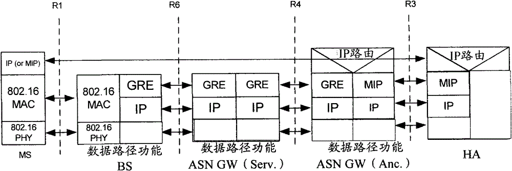
[0104] Below to Figure 7 For reference, the downlink data transmission method is described in detail.
[0105] First, the ASN GW establishes a GRE tunnel that terminates at the ARS via the ABS, and each connection of the AMS has a one-to-one mapping relationship with the GRE key on the GRE tunnel; when the ASN GW establishes the GRE tunnel, it needs to refer to the ARS and the ASN GW path information between them.
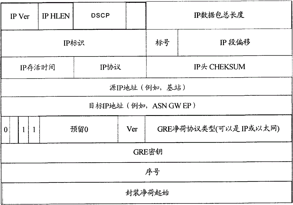
[0106] One or more relay service flow connections for data transmission are established between the ARS and the ABS, and a mapping relationship is established between the service flows of the AMSs and the relay service flow connections according to QoS level parameters. In addition, there is also a mapping relationship between the DSCP value on the GRE / IP encapsulation between the ABS and the ASN GW and the relay service flow according to the QoS level parameter. From this, it can be obtained that AMSs service flow, relay service flow between ARS and ABS, and GR...
example 3
[0111] For uplink data transmission, the basic process is similar to downlink data transmission, and the detailed process includes:
[0112] Step 1: ARS establishes a GRE tunnel between the BS and the ASN GW. The addresses of the two ends of the GRE tunnel are the IP addresses of the ARS and the ASN GW respectively. Among them, the radio bearer is between the ARS and the ABS, and the IP address between the ABS and the ASN GW is Wired bearer; after the GRE tunnel is established, the service flow of the AMS is carried on the GRE tunnel when it is transmitted between the ARS and the ASN GW, and different service flow connections correspond to different GRE keys.
[0113] Step 2: After receiving the uplink MAC PDU data from the AMS, the ARS maps one or more service flows to the uplink GRE tunnel, that is, performs GRE / IP encapsulation and header compression on the payload in the MAC PDU, and sends After it is encapsulated into a Relay MAC PDU, it is sent on the air interface link ...
PUM
 Abstract
Description
Claims
Application Information
 - R&D
- Intellectual Property
- Life Sciences
- Materials
- Tech Scout
- Unparalleled Data Quality
- Higher Quality Content
- 60% Fewer Hallucinations
Browse by: Latest US Patents, China's latest patents, Technical Efficacy Thesaurus, Application Domain, Technology Topic, Popular Technical Reports.
© 2025 PatSnap. All rights reserved.Legal|Privacy policy|Modern Slavery Act Transparency Statement|Sitemap|About US| Contact US: help@patsnap.com