
Current measuring device and method

A current measuring device and current technology, applied in the direction of measuring devices, measuring electrical variables, measuring current/voltage, etc., can solve problems such as inability to compensate, low measurement repeatability, and irregular interference factors

Inactive Publication Date: 2011-05-18
SIEYUAN ELECTRIC CO LTD
View PDF3 Cites 43 Cited by
  • Summary
  • Abstract
  • Description
  • Claims
  • Application Information

AI Technical Summary

Problems solved by technology

[0008] The purpose of the present invention is to provide a current measuring device and a current measuring method to solve the problem that when using the current measuring method of the prior art to measure a circuit, the interference factors in the measurement are not regular and cannot be compensated, which leads to low repeatability of the measurement. low problem

Method used


Image

  • Current measuring device and method
  • Current measuring device and method
  • Current measuring device and method

Examples


Embodiment Construction

[0020] The embodiments of the present invention will be described in detail below with reference to the accompanying drawings, but the present invention can be implemented in many different ways defined and covered by the claims.

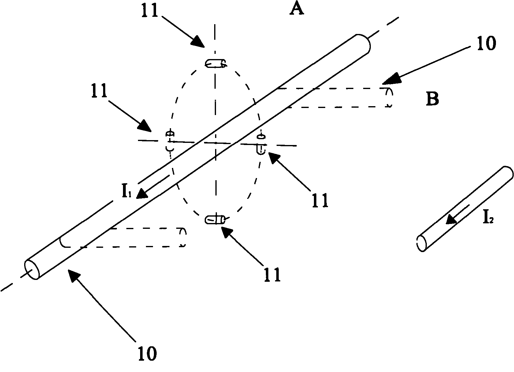
[0021] Combine below figure 1 and figure 2 Embodiment 1 of the present invention will be described in detail.

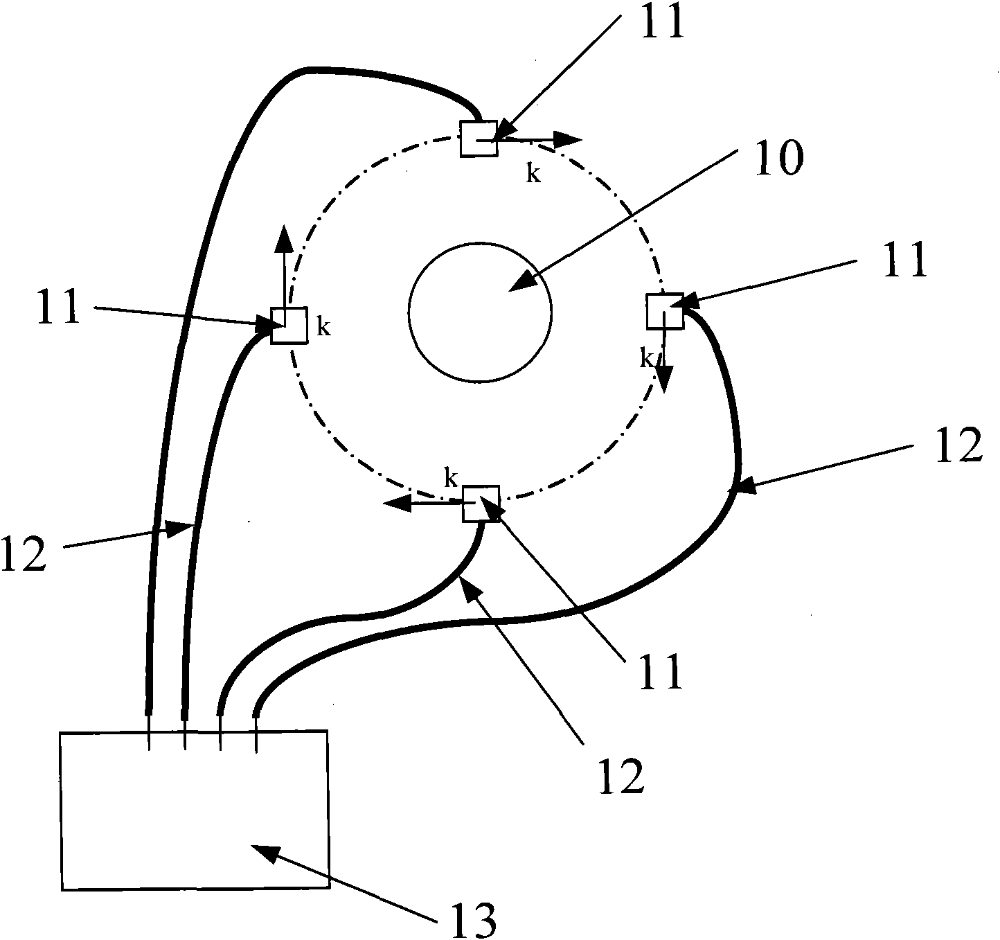
[0022] figure 1 A block diagram of the cross-sectional structure of the current measuring device according to Embodiment 1 of the present invention is shown. Such as figure 1 As shown, the current measuring device in this embodiment is a current measuring device including four magnetic field sensors.

[0023] The current measurement device shown in this embodiment includes: four magnetic field sensors 11 , a signal transmission part 12 and a signal processing module 13 .

[0024] Wherein, four magnetic field sensors 11 are equidistantly distributed on the outside of the measured conductor 10, and each magnetic field sensor 11 is used...


PUM


Abstract

The invention provides a current measuring system and method, wherein the current measuring system comprises two or more magnetic field sensors and a signal processing module; the magnetic field sensors are distributed at the outer side of a measured conductor at equal distance, and each magnetic field sensor is used for acquiring the magnetic density of an induction field generated by a current flowing through the measured conductor; the signal processing module is connected with each signal transmission module through signal transmission parts and is used for linearly summarizing the acquired magnetic densities and calculating the value of the current in the measured conductor based on the summarized magnetic density by summarization. The invention lowers the influence of the shape of the conductor on the acquired magnetic density and the influence of an external current source on a measurement result, therefore, the problem of lower repeatability precision for measurement, caused by irregularity and incapability of compensating interference factors in measurement of circuits by utilizing a current measurement way in the prior art, is solved.

Description

technical field [0001] The invention relates to the field of test and measurement, in particular to a current measuring device and a current measuring method. Background technique [0002] In high-voltage high-power DC or AC power transmission, the use of optical methods to measure the current on high-voltage transmission lines has attracted widespread attention. The development and application of various photoelectric current transformers based on optical fiber technology has received widespread international attention. [0003] In high-voltage high-power DC or AC power transmission, magneto-optical effects such as the Faraday effect are mainly used to measure the current on the high-voltage transmission line. [0004] The corresponding relationship between the magnetic field and the current is shown in formula (1): [0005] [0006] In the formula, the left side is the current in the conductor, and the right side is the closed-loop integral of the magnetic field streng...

Claims


Application Information

Patent Timeline
IPC IPC(8): G01R19/00G01R19/04
CPCG01R15/247G01R15/207
Inventor 袁海骏韩小逸杨德志欧阳翔
Owner SIEYUAN ELECTRIC CO LTD
Learn More