
Method of detecting filling of hydraulic clutch

A hydraulic clutch, friction clutch technology, applied in clutches, fluid-driven clutches, non-mechanical-driven clutches, etc., can solve problems such as uneven shift transmission lockup, engine knocking, etc.

Active Publication Date: 2011-05-18
GM GLOBAL TECH OPERATIONS LLC
View PDF5 Cites 14 Cited by
  • Summary
  • Abstract
  • Description
  • Claims
  • Application Information

AI Technical Summary

Problems solved by technology

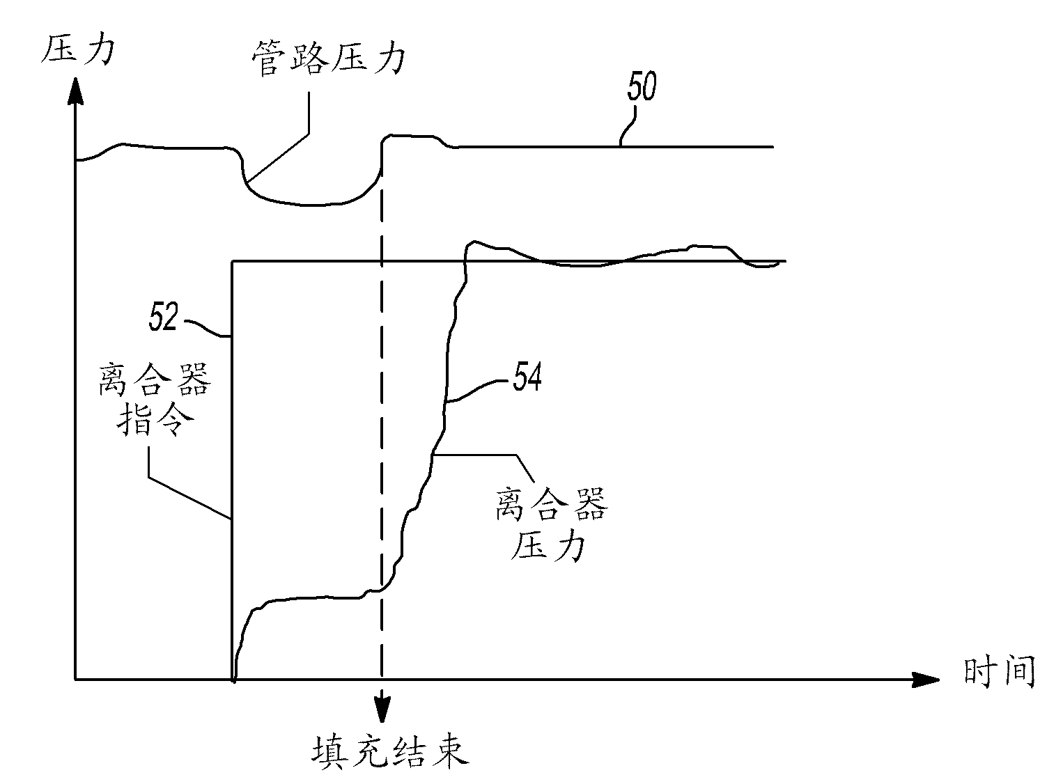
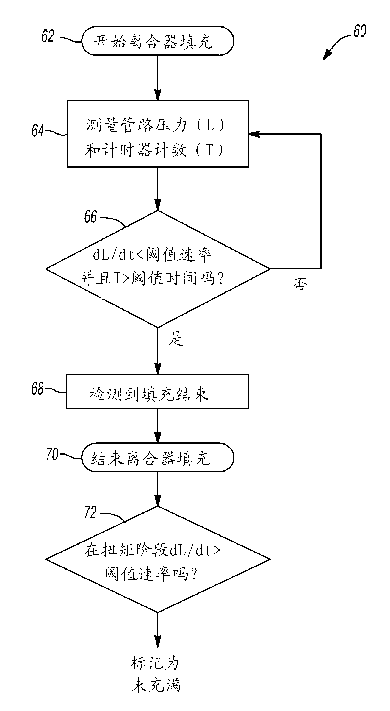
[0006] In this type of transmission, if clutch pressure control is initiated when the clutch chamber is not completely filled with transmission oil, it may cause engine knock when the engine speed suddenly increases due to lack of load
Similarly, when the clutch fill phase is longer than necessary, sudden uncontrolled engagement of the clutch can cause and cause jerky shifts or transmission lockup

Method used


Image

  • Method of detecting filling of hydraulic clutch
  • Method of detecting filling of hydraulic clutch
  • Method of detecting filling of hydraulic clutch

Examples


Embodiment Construction

[0058] The following description is merely exemplary in nature and does not limit the disclosure, application or uses thereof.

[0059] Reference attached figure 1 , shows a portion of an automatic transmission incorporating the present invention, which is generally indicated by reference numeral 10 . Automatic transmission 10 includes a rotatable input shaft 14 that provides drive torque from a prime mover (not shown), such as a gasoline engine, diesel engine, flex fuel engine, hybrid or electric machine, to a clutch pack 16 . It should be understood that the clutch pack 16 is representative only, that multiple clutches are typically used in a transmission, and that clutch locations may be at the input of the transmission, within the transmission, or both. The clutch assembly 16 includes a hydraulic cylinder 18 that houses a hydraulic apply piston 22 that is slidable in both directions. The hydraulic apply piston 22 acts on and compresses or releases an associated friction ...


PUM


Abstract

The invention relates to a method of detecting filling of hydraulic clutch. Concretely, a method of detecting substantial filling of a hydraulic cylinder of a hydraulically operated clutch of a vehicular transmission is disclosed and claimed. A pressure sensor disposed in a hydraulic line to the clutch cylinder provides a signal that the hydraulic pressure has dropped as the clutch cylinder begins to fill and also that the pressure has returned to a substantially normal level. The pressure sensor may be a continuously variable output such as an analog sensor, pulse width modulation (PWM) sensor, a similar device or, less desirably, a two state sensor. An iterative algorithm utilizes data from the sensor and a timer to determine when clutch fill is substantially complete.

Description

technical field [0001] The present disclosure relates to methods of operating hydraulic clutches, and more particularly, to methods for detecting fill completion of hydraulic clutches in vehicle transmissions. Background technique [0002] The statements in this section merely provide background information related to the present disclosure and may or may not constitute prior art. [0003] In many automatic transmissions, a hydraulic piston and cylinder assembly engages and disengages clutches to achieve a desired power flow path corresponding to a desired gear ratio or speed, usually in order of the gear ratios or speeds. This operation occurs in clutch-to-clutch (multi-planetary) and dual-clutch (DCT) transmissions. [0004] In such transmissions, the smoothness and overall quality of the shift is primarily determined by the clutch engagement characteristics, eg, how soon after the clutch engagement command begins the clutch engagement and how quickly the clutch engages. ...

Claims


Application Information

Patent Timeline
IPC IPC(8): G01M13/02G01L19/08F16D25/062F16H61/02
CPCF16D48/066F16H2306/36F16D2500/30401F16D2500/3024F16D2500/70414
Inventor V·A·尼拉肯坦B·M·奥尔森
Owner GM GLOBAL TECH OPERATIONS LLC
Learn More