


Quick Research
Generate reliable direction feasibility study reports for your R&D in just a few steps.

Technical Q&A
Discover and master advanced knowledge NOW. Basics, ideas, possibilities, all at once.

Find Solutions
As an expert in R&D theories, this can generate solutions to your technical problems instantly.

Evaluate Feasibility
Analyze your overall solution with one click, know your potential R&D risks in advance.

Monitor Landscape
Get weekly tech updates, stay abreast of the latest tech innovations and key insights.
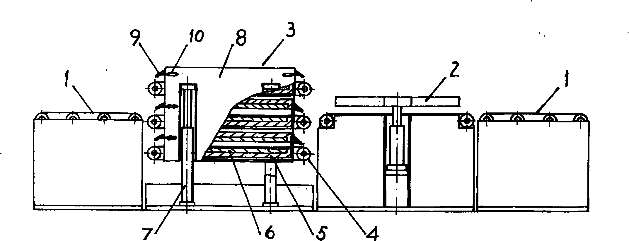
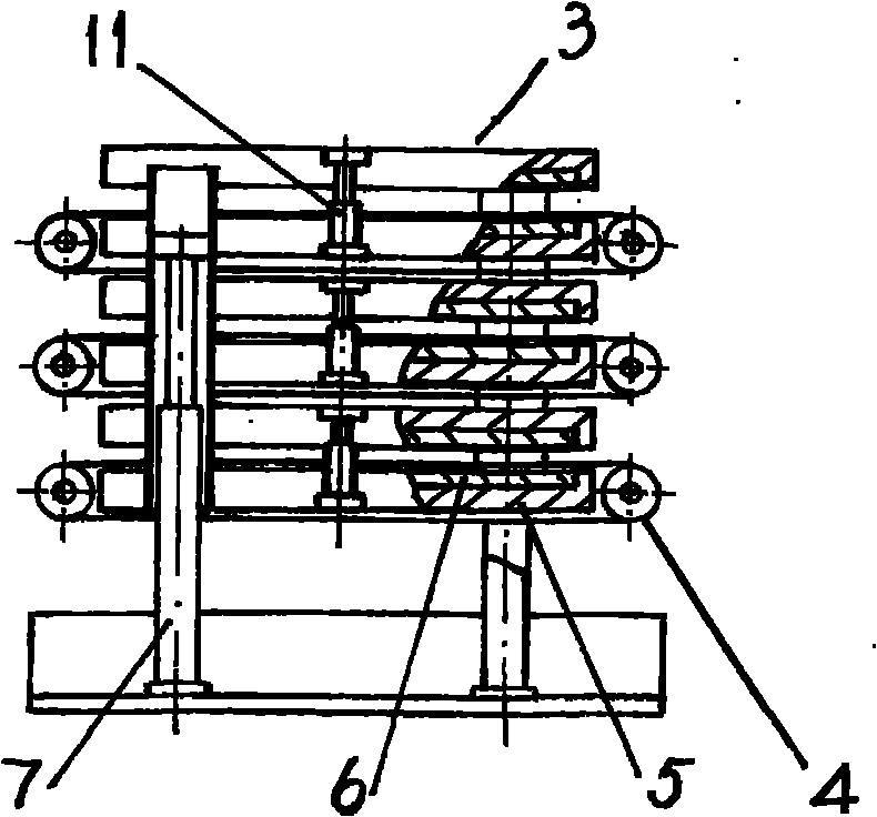
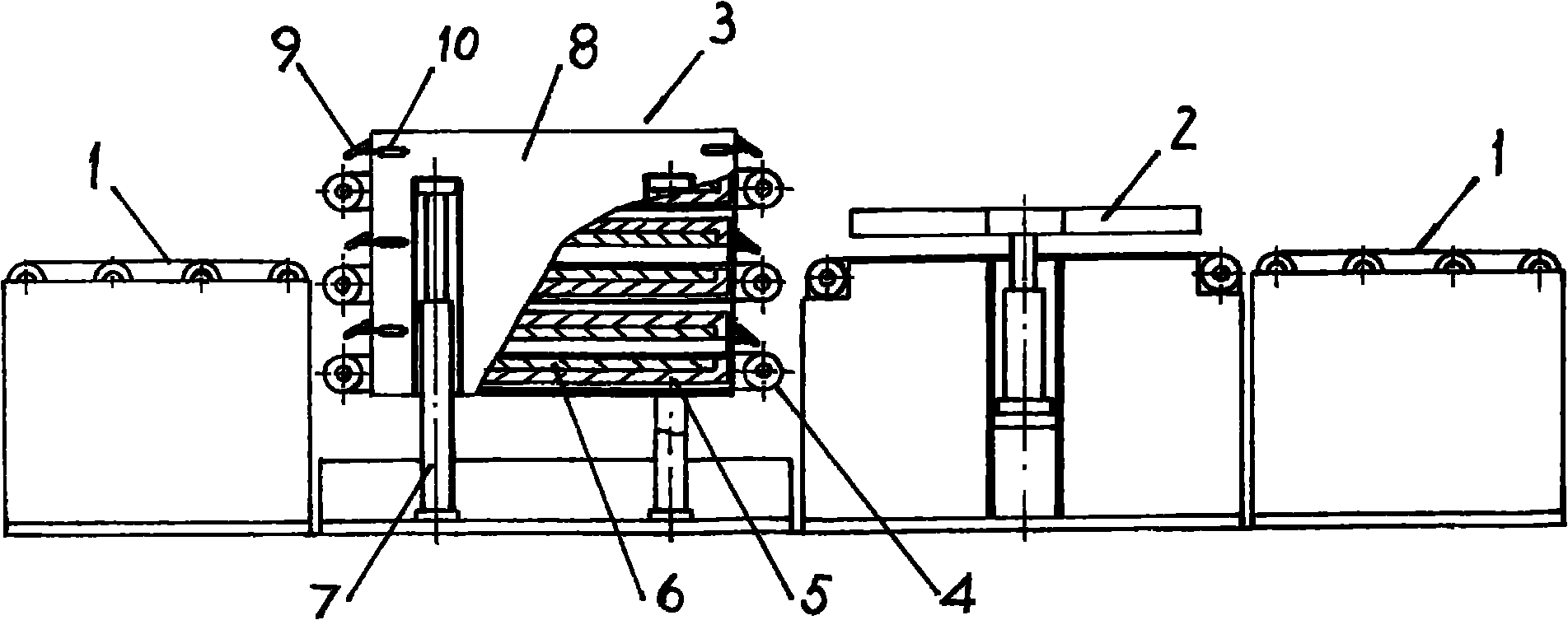
Laminated curing equipment of solar-cell panel
A solar panel, lamination and curing technology, applied in the direction of lamination, lamination auxiliary operation, layered products, etc., can solve the problem of limiting the production efficiency of solar panel lamination and curing equipment, curing heating temperature, high heating temperature, difficult to guarantee The problem of uniform heating of the battery board can achieve the effect of simple structure, uniform heating and convenient temperature control.
- Summary
- Abstract
- Description
- Claims
- Application Information
AI Technical Summary
Problems solved by technology
Method used
Image

Examples
Embodiment Construction
[0013] The specific embodiments of the present invention will be described with reference to the accompanying drawings.
[0014] as attached figure 1 , The solar cell panel lamination and curing equipment has a conveying table 1 placed at the front and the rear respectively. The conveying table in the embodiment of the drawings is mainly composed of main and driven rollers located at both ends, idler rollers and circulating conveyor belts distributed between the main and driven rollers. Not limited to this, any transport table that can transport solar panels from the front end to the rear end can be used as the transport table of the lamination curing equipment. A belt conveyor laminator 2 is connected behind the front conveyor table 1. The belt conveyor laminator is a solar cell equipped with a circulating conveyor belt and driven by a lifting cylinder to cooperate with the upper lamination chamber and the lower lamination chamber to complete the lamination. Board laminatio...
PUM
 Abstract
Description
Claims
Application Information
 - R&D Engineer
- R&D Manager
- IP Professional
- Industry Leading Data Capabilities
- Powerful AI technology
- Patent DNA Extraction
Browse by: Latest US Patents, China's latest patents, Technical Efficacy Thesaurus, Application Domain, Technology Topic, Popular Technical Reports.
© 2024 PatSnap. All rights reserved.Legal|Privacy policy|Modern Slavery Act Transparency Statement|Sitemap|About US| Contact US: help@patsnap.com