
Split liquid crystal television and realizing method thereof

A technology for a liquid crystal TV and an implementation method, which is applied in the directions of TVs, color TVs, and components of color TVs, etc., can solve the problems of reducing the thickness of the TV, reducing the appearance of the narrow frame, and scrapping the liquid crystal screen.

Active Publication Date: 2011-05-11
深圳康佳控股集团有限公司
View PDF6 Cites 10 Cited by
  • Summary
  • Abstract
  • Description
  • Claims
  • Application Information

AI Technical Summary

Problems solved by technology

[0003] The present invention solves the problem that the existing liquid crystal TV adopts the method of moving the power supply and the circuit board from the back of the screen to the side of the screen to reduce the thickness of the TV. It is impossible to achieve ultra-thin and narrow frame at the same time, which affects the appearance, and the backlight part damages the entire liquid crystal. To solve the defects of scrapped screens, a split LCD TV and its realization method are provided, by setting the LCD module, backlight module, and TV signal box separately, and embedding the backlight module, TV signal box into the wall or TV cabinet Body, effectively realize the ultra-thin LCD TV, maintain the overall appearance, and facilitate the maintenance and replacement of the backlight module

Method used


Image

  • Split liquid crystal television and realizing method thereof
  • Split liquid crystal television and realizing method thereof
  • Split liquid crystal television and realizing method thereof

Examples


Embodiment Construction

[0021] The implementation of the present invention is different from the implementation of the traditional ultra-thin TV. Such as figure 2 , 6 As shown in 7, 7, and 8, the present invention innovatively separates the LCD module 16, the backlight module 15, and the TV signal box 14 (TV module), and makes full use of the space of the indoor wall or cabinet 13 , The backlight module 15 and the TV signal box 14 are each independently arranged as a whole, and stored into the wall or cabinet 13 (such as Figure 8 ). The liquid crystal cell 2 in the liquid crystal module 16 uses tempered glass or the like as the supporting glass back plate 5, and also plays a protective role, so that the fragile liquid crystal screen can be separated from the backlight module 15 independently.

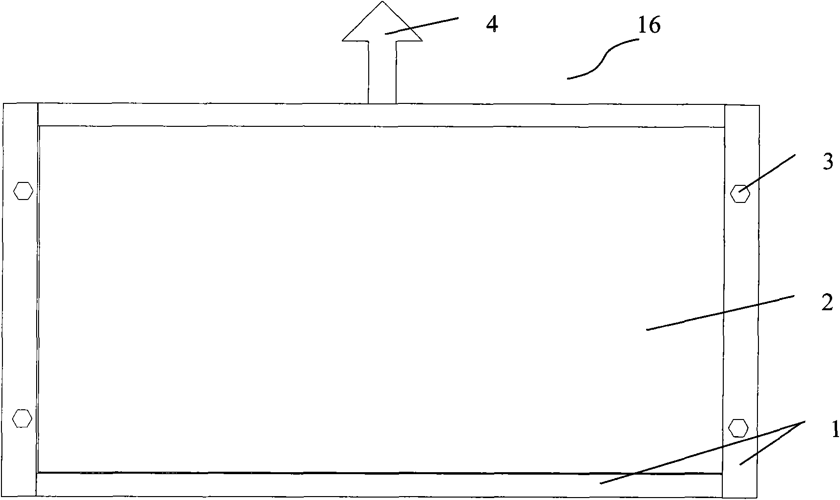
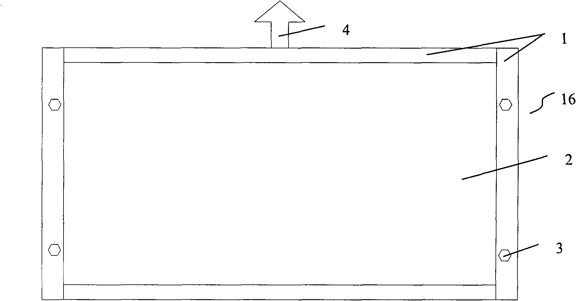
[0022] Such as figure 1 , 2 3, the liquid crystal module 16 part includes the liquid crystal CELL 2, the supporting glass back plate 5, the outer frame 1, the mounting screw hole 3 and other parts. The liquid...


PUM


Abstract

The invention discloses a split liquid crystal television and a realizing method thereof. The split liquid crystal television comprises a liquid crystal module, a backlight module and a television signal box, which are split, wherein the liquid crystal module comprises a liquid crystal CELL and a supporting glass back plate, which are tightly pressed against and matched in shape with each other; an outer frame I is arranged on the edges of the liquid crystal cell and the supporting glass back plate; the backlight module comprises a square outer frame II, and a protective layer, an optical film, a diffusion plate, a lamp tube and a back plate are arranged in turn in the outer frame II along the opening direction of the outer frame II; and the television signal box comprises a television circuit, a power supply, and a lamp driving and TCON signal processing circuit. The liquid crystal television can be made ultrathin by accommodating a backlight module and a television signal box in an indoor wall body or a television cabinet; more importantly, the backlight module can be used alone for lighting, and the liquid crystal cell and the backlight module are partially separated, so the maintenance and replacement of the lamp tube of the backlight module are as simple as the replacement of a fluorescent lamp tube at home.

Description

Technical field [0001] The invention relates to the field of flat display, in particular to a liquid crystal television. Background technique [0002] With the development of flat-panel display technology, the trend of flat-panel TVs is getting thinner and thinner, and ultra-thin TVs have become the goal that everyone pursues. At present, the realization of ultra-thin TV has not been out of the scope of traditional TV. The implementation method usually thins the components in the TV. There are ways to reduce the thickness of the LCD screen, reduce the thickness of the power supply, and reduce the thickness of the internal circuit board of the TV. These methods can only reduce the thickness of the TV to a certain limit. Reducing and reducing the thickness of the screen will sacrifice some of the optical characteristics of the screen. Taking the LCD screen as an example, reducing the thickness of the backlight module will make it possible to see the mura of some backlights on the ...

Claims


Application Information

Patent Timeline
IPC IPC(8): H04N5/44G02F1/13G09G3/36
Inventor 姜洪波
Owner 深圳康佳控股集团有限公司
Learn More