
Electric wheel hub motor

A hub motor and electric vehicle technology, applied in electric vehicles, motors, electric components, etc., can solve problems such as unsatisfactory braking effect, weak braking force, heavy hub motor weight, etc., and achieve good braking effect

Inactive Publication Date: 2011-05-11
SUZHOU EAGLE ELECTRIC VEHICLE MFG
View PDF0 Cites 5 Cited by
  • Summary
  • Abstract
  • Description
  • Claims
  • Application Information

AI Technical Summary

Problems solved by technology

[0002] At present, the brakes of electric vehicles generally adopt hub-type brakes. The structure is to install a brake pad outside the drum-shaped bowl on the electric wheel rim. When braking, the operator holds the brake handle and pulls the brake line, thereby expanding the brake pad and supporting The drum-shaped bowl on the wheel circle achieves the purpose of braking. Although the structure of the brake is simple, the braking force is weak, especially when it is installed on an electric vehicle. Compared with a motor vehicle, an electric vehicle has a much larger weight. In addition, the weight of the wheel hub motor itself is relatively large, so the inertia is particularly large during high-speed operation. If the hub type brake is used, the brake line is only pulled by the handle, and the brake pad is expanded to support the drum-shaped bowl to achieve the purpose of braking. The power is limited and the brake line consumes part of the tension, so the braking effect is not ideal

Method used


Image

  • Electric wheel hub motor
  • Electric wheel hub motor
  • Electric wheel hub motor

Examples


Embodiment Construction

[0013] Below in conjunction with accompanying drawing, the present invention is described in further detail:

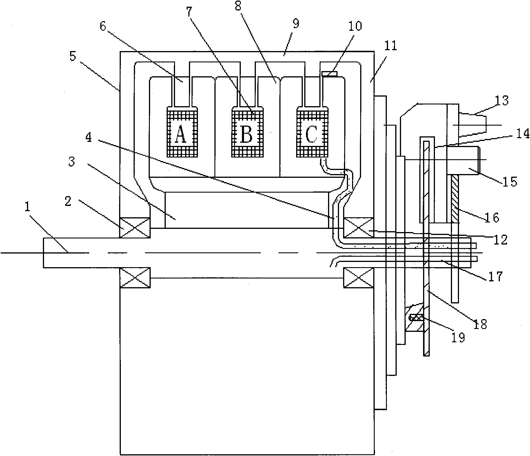
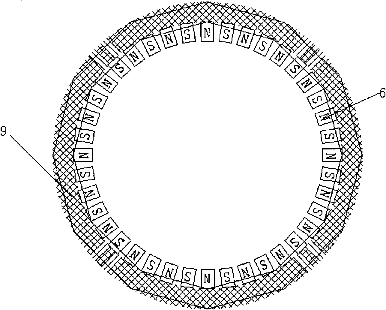
[0014] like figure 1 As shown, the present invention includes a shaft 1, bearings 2 and 12, a bracket 3, a permanent magnet pole 6, an armature winding 7, a silicon steel sheet yoke 8 and a casing 5, and the casing 5 includes a side wall 9 and an end cover 11. The bearings 2 and 12 are set on the shaft 1, the permanent magnet poles 6 are bonded on the side wall 9, the end cover 11 is connected with the bearings 2 and 12, and together with the permanent magnet poles 6 form the motor rotor; the armature winding 7, the silicon steel sheet The yoke 8 and the bracket 3 are fixedly connected with the shaft 1 to serve as a motor stator. The lead wire 4 and the winding tap lead wire are drawn out of the hollow part of the shaft 1 and connected with the additionally equipped open-loop controller. A Hall position sensor 10 is arranged on the silicon steel sheet yoke close to ...


PUM


Abstract

The invention discloses an electric wheel hub motor which comprises a shell, a motor arranged in the shell, and a disc brake which comprises a disc brake disk and a pair of brake sheets, the disc brake disk is fixed on an output shaft of the motor, and rotates synchronously with the motor; and the disc brake is fixed on an electrombile body; the pair of brake sheets are respectively and relatively arranged on two sides of one end of the disc brake disk, strong force action of a hydraulic pump is utilized in the structure, the brake sheets are driven to clamp the disc brake disk, thereby reaching a favorable braking effect.

Description

technical field [0001] The invention relates to an electric hub motor, in particular to a hub motor with a disc brake device. Background technique [0002] At present, the brakes of electric vehicles generally adopt hub-type brakes. The structure is to install a brake pad outside the drum-shaped bowl on the electric wheel rim. When braking, the operator holds the brake handle and pulls the brake line, thereby expanding the brake pad and supporting The drum-shaped bowl on the wheel circle achieves the purpose of braking. Although the structure of the brake is simple, the braking force is weak, especially when it is installed on an electric vehicle. Compared with a motor vehicle, an electric vehicle has a much larger weight. In addition, the weight of the wheel hub motor itself is relatively large, so the inertia is particularly large during high-speed operation. If the hub type brake is used, the brake line is only pulled by the handle, and the brake pad is expanded to suppor...

Claims


Application Information

Patent Timeline
IPC IPC(8): H02K7/10H02K1/17H02K29/06
CPCY02T10/64
Inventor 吴国军
Owner SUZHOU EAGLE ELECTRIC VEHICLE MFG
Learn More