
Electric motor and/or generator with mechanically tuneable permanent magnetic field

A technology for electric motors and generators, applied in the direction of magnetic circuit rotating parts, magnetic circuit shape/style/structure, etc., can solve problems such as low operating efficiency

Inactive Publication Date: 2011-05-11
路易斯・J・芬克尔
View PDF8 Cites 8 Cited by
  • Summary
  • Abstract
  • Description
  • Claims
  • Application Information

AI Technical Summary

Problems solved by technology

A similar problem exists in wind turbines, where variations in wind speed encountered result in inefficiencies in operation

Method used


Image

  • Electric motor and/or generator with mechanically tuneable permanent magnetic field
  • Electric motor and/or generator with mechanically tuneable permanent magnetic field
  • Electric motor and/or generator with mechanically tuneable permanent magnetic field

Examples


Embodiment Construction

[0069] The following description is of the best mode currently contemplated for carrying out the invention. This description is not presented in a limiting sense, but merely for the purpose of describing one or more preferred embodiments of the invention. The scope of the invention should be determined with reference to the claims.

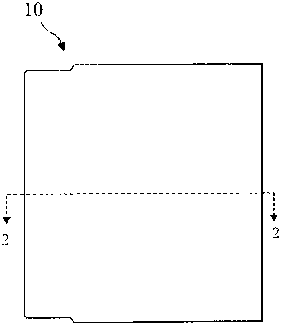
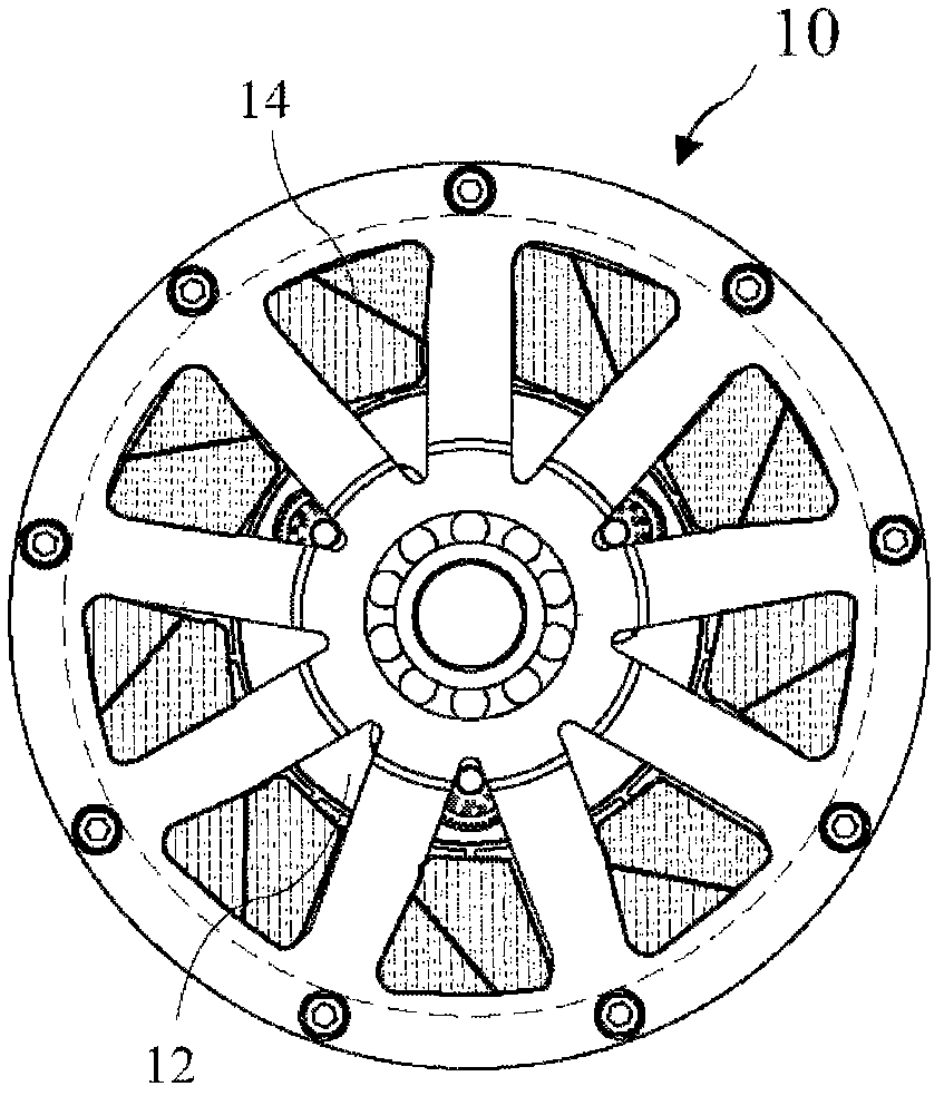
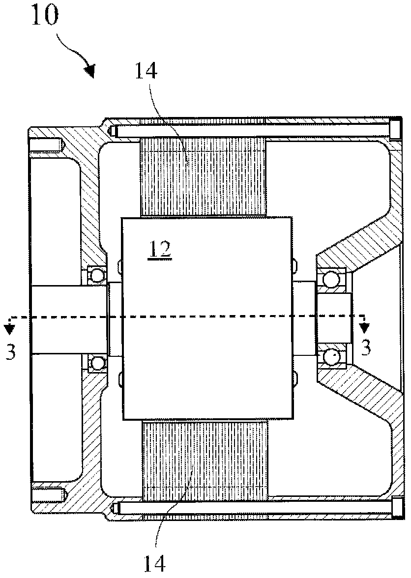
[0070] Figure 1A shows a side view of a reconfigurable electric motor 10 according to the invention, Figure 1B An end view of a reconfigurable electric motor 10 is shown, figure 2 shows along the Figure 1A A cross-sectional view of the reconfigurable electric motor 10 taken at line 2-2 in FIG. The motor 10 comprises a stator winding 14 and a rotor 12 inside the stator winding. The motor 10 is a brushless AC induction motor comprising a magnetic circuit comprising at least one permanent magnet 16 in a rotor 12 (see image 3 -7) or removable magnetic shunt block 80 (see Figure 30A and 30B ), the magnet 16 or magnetic shunt block 80 can be...


PUM


Abstract

The invention discloses an apparatus and a method for tuning the magnetic field of brushless motors and alternators to obtain efficient operation over a broad RPM range. The motor or alternator comprises fixed windings (or stator) around a rotating rotor carrying permanent magnets. The permanent magnets are generally cylindrical and have North and South poles formed longitudinally in the magnets. Magnetically conducting circuits are formed by the magnets residing in magnetic conducting pole pieces (for example, low carbon or soft steel, and / or laminated insulated layers, of non-magnetizable material). Rotating the permanent magnets, or rotating non-magnetically conducting shunting pieces, inside the pole pieces, either strengthens or weakens the resulting magnetic field to adjust the motor or alternator for low RPM torque or for efficient high RPM efficiency. Varying the rotor magnetic field adjusts the voltage output of the alternators allowing, for example, a windmill generator, to maintain a fixed voltage output.

Description

technical field [0001] This application is a continuation-in-part of U.S. Patent Application Serial No. 12 / 610,184, filed October 30, 2009, and U.S. Patent Application Serial No. 12 / 610,271, filed October 30, 2009, both of which are The contents are incorporated into this application by reference. Background technique [0002] The present invention relates to electric motors and generators, and more particularly to adjusting the orientation of stationary magnets and / or non-magnetic shunt blocks in a rotor for efficient operation at various RPMs. [0003] Brushless DC motors are generally required to operate at a wide range of RPMs, but can only be operated efficiently over a limited RPM range. Furthermore, generators and alternators are often required to operate over a wide range of revolutions per minute. For example, automotive alternators operate at RPM proportional to engine RPM, while wind alternators operate at RPM proportional to wind speed. Unfortunately, known al...

Claims


Application Information

Patent Timeline
IPC IPC(8): H02K1/22H02K1/27
Inventor 路易斯·J·芬克尔安德烈亚·富里亚
Owner 路易斯・J・芬克尔
Learn More