


Quick Research
Generate reliable direction feasibility study reports for your R&D in just a few steps.

Technical Q&A
Discover and master advanced knowledge NOW. Basics, ideas, possibilities, all at once.

Find Solutions
As an expert in R&D theories, this can generate solutions to your technical problems instantly.

Evaluate Feasibility
Analyze your overall solution with one click, know your potential R&D risks in advance.

Monitor Landscape
Get weekly tech updates, stay abreast of the latest tech innovations and key insights.
Crane with a boom tensioning device
A crane and jib technology, applied in the field of cranes, can solve problems such as inability to achieve three-dimensional tensioning, and achieve the effects of improving lateral tensioning and good three-dimensional tensioning
- Summary
- Abstract
- Description
- Claims
- Application Information
AI Technical Summary
Problems solved by technology
Method used
Image

Examples
Embodiment Construction
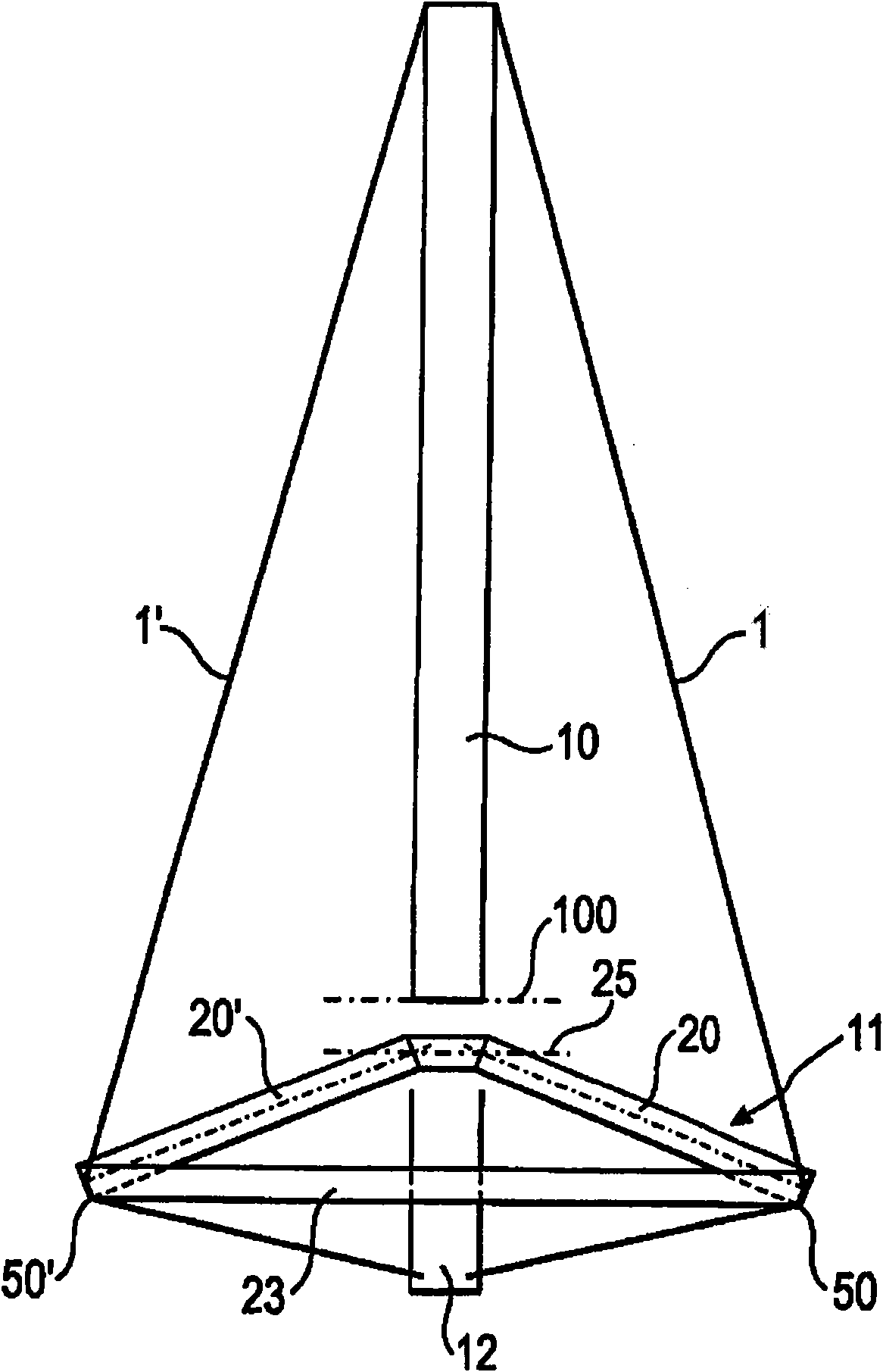
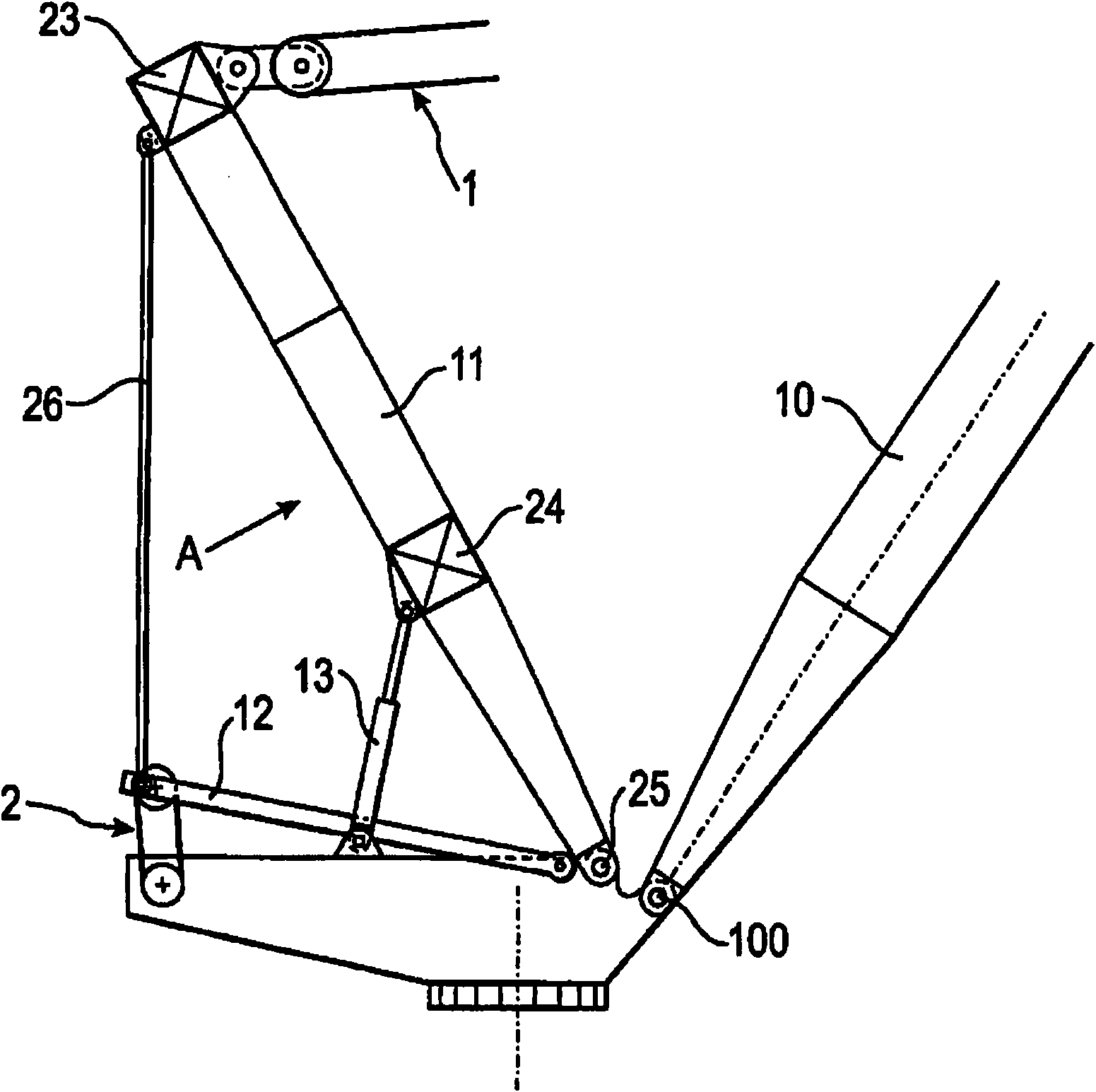
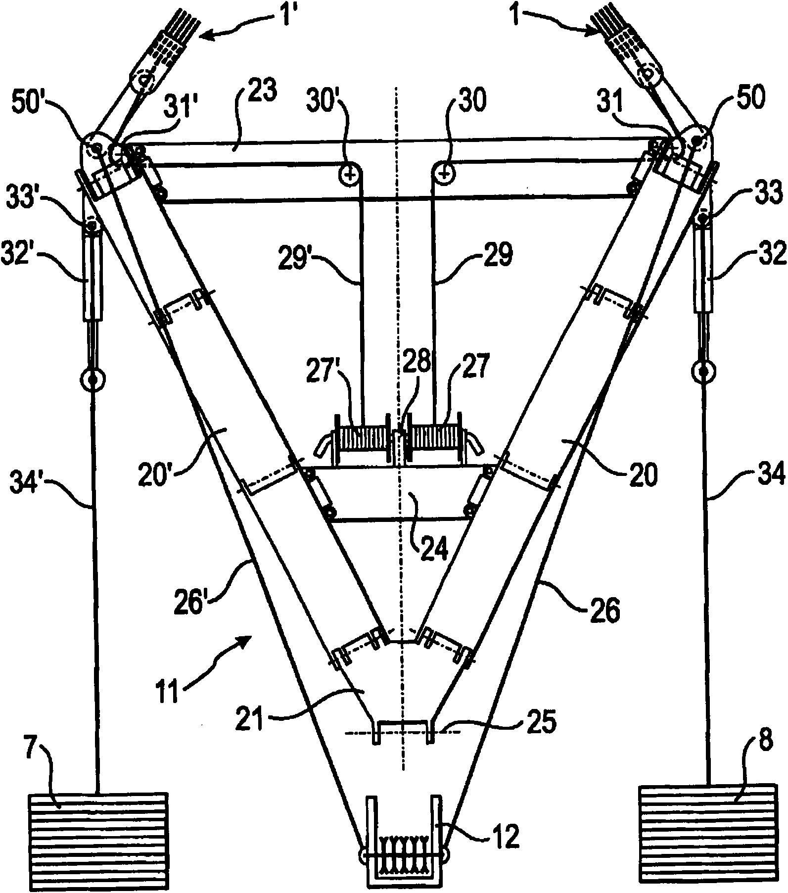
[0042] figure 1 An embodiment of the crane according to the invention is shown in plan view. Here, a main boom 10 is provided, which is mounted pivotably about an axis 100 on the upper carriage. In addition, a cable jib mechanism 11 is provided, which is likewise articulated on the upper carriage. The main boom 10 may now be in the form of a truss jib.
[0043] Furthermore, the boarding itself is in figure 1 is not shown. The entry carriage is now mounted on an exit carriage, also not shown. Furthermore, a running gear is provided on the lower carriage 52 for traveling the crane, for example a crawler running gear or a plurality of axles with tires.
[0044] A cable winding system is provided between the cable jib mechanism 11 and the main boom 10 . The cable reel system now comprises a first cable 1 which extends from a tension point 50 on the cable jib mechanism 11 to the main boom 10 . Furthermore, the cable reeling system comprises a second cable 1' which extends fr...
PUM
 Abstract
Description
Claims
Application Information
 - R&D Engineer
- R&D Manager
- IP Professional
- Industry Leading Data Capabilities
- Powerful AI technology
- Patent DNA Extraction
Browse by: Latest US Patents, China's latest patents, Technical Efficacy Thesaurus, Application Domain, Technology Topic, Popular Technical Reports.
© 2024 PatSnap. All rights reserved.Legal|Privacy policy|Modern Slavery Act Transparency Statement|Sitemap|About US| Contact US: help@patsnap.com