Stamped and welded semi-open impeller centrifugal pump

A stamping and welding, semi-open technology, applied in the field of stamping and welding semi-open impeller centrifugal pumps, can solve the problems of increasing the difficulty of manufacturing the pump casing, the cost and the manufacturing time, increasing the difficulty of producing the impeller blades, and the high requirement of the strength of the pump casing. , to achieve the effect of good passability, good strength and rigidity, and easy flow path

Active Publication Date: 2013-02-06
GUANGDONG WINNING PUMPS INDAL
View PDF2 Cites 0 Cited by
  • Summary
  • Abstract
  • Description
  • Claims
  • Application Information

AI Technical Summary

Problems solved by technology

Although the stamping and welding food pump forms an end face sealing structure between the impeller and the pump casing to improve its sealing performance, the structure still has the following disadvantages: 1) The structure of the pump casing is complicated, the manufacturing process requirements are improved, and the The manufacturing difficulty, cost and manufacturing time of the pump casing; 2) Since the end face matched between the impeller and the pump casing is an inclined surface, it is required that the front end face of the blade must be parallel to the front casing of the pump casing, which increases the production of impeller blades difficulty
Researchers in the field know that if the direction of the outlet pipe is designed along the tangent direction of the pump casing, the impact loss of the liquid in the pump casing can be reduced, but the strength of the pump casing is very high and the process structure is very complicated.

Method used


Image

  • Stamped and welded semi-open impeller centrifugal pump
  • Stamped and welded semi-open impeller centrifugal pump
  • Stamped and welded semi-open impeller centrifugal pump

Examples


Embodiment Construction

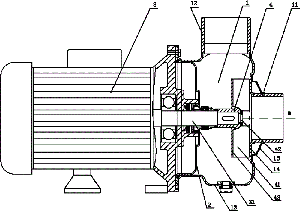
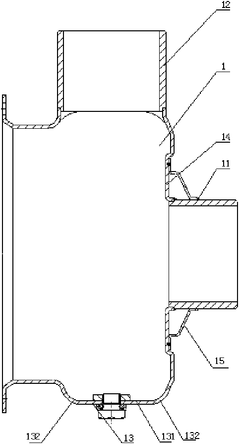
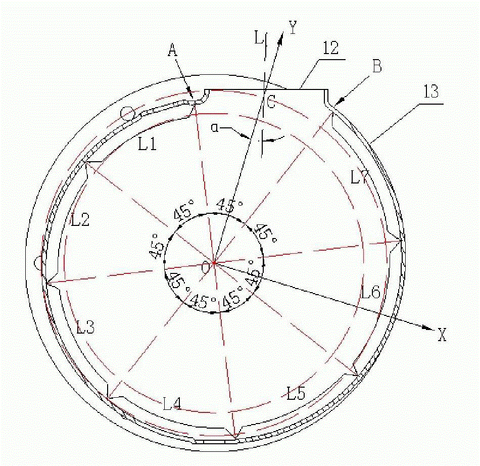
[0027] Such as Figure 1 to Figure 3 As shown, the stamping and welding semi-open impeller centrifugal pump of the present invention includes a pump body 1, a pump back cover 2, a motor 3 installed at the open end of the pump body, and an impeller 4 arranged in the pump body 1. The impeller 4 is installed The pump shaft 31 is driven to rotate by a motor 3. The pump body 1 is provided with a water inlet pipe 11 and a water outlet pipe 12. The water inlet pipe 11 and the pump shaft 31 are coaxially mounted on the outer side of the axial surface 13 of the pump body. The impeller 4 is a semi-open structure and is composed of blades 41, a hub 42 and a rear cover 43. The front end surface of the blade 41 and the axial surface 14 of the pump body close to the front end surface are respectively perpendicular to the axial direction of the pump body. The distance between the front end face of the blade 41 and the axial face of the pump body is not more than 2 mm, forming an end face seal...


PUM


Abstract

The invention discloses a stamped and welded semi-open impeller centrifugal pump. The centrifugal pump comprises a pump body, a rear pump cover, a motor and an impeller, wherein the rear pump cover is arranged at an open end of the pump body; the impeller is arranged in the pump body, arranged on a pump shaft and driven by the motor to rotate; the pump body is provided with a water inlet pipe and a water outlet pipe; the water inlet pipe and the pump shaft are coaxially arranged outside the axial surface of the pump body; the impeller has a semi-open structure and consists of blades, a wheel hub and a rear cover plate; the front end faces of the blades and the axial surface of the pump body close to the front end faces are planes which are perpendicular to the axial direction of the pump body, and the front end faces and the axial surface are sealed; on the plane formed by the diameter of the pump body in the direction perpendicular to the axis of the water inlet pipe, the axis of the water outlet pipe does not pass through the center of the pump body, and the included angle alpha between the axis of the water outlet pipe and the radial direction of the pump body is more than 0 degree and less than 18 degrees; and the radial direction is the radius direction from the crossing point of the axis of the water outlet pipe and the pump body to the center of the pump body. The centrifugal pump has the advantages of improving hydraulic efficiency, strength and stiffness, along with convenience of production by a stamping process and smooth flow passage.

Description

Technical field [0001] The invention relates to a pump, in particular to a stamping and welding semi-open impeller centrifugal pump. Background technique [0002] Stamped and welded centrifugal pumps are generally welcomed by consumers because of their light structure, material saving, high efficiency, no pollution, and low cost. However, in the prior art, the stamping and welding semi-open impeller centrifugal pump still has some shortcomings, especially the sealing problem at the entrance of the impeller, which has not been well solved. Due to deficiencies in strength, rigidity, machining accuracy, etc., the impeller has a large radial runout during operation. Therefore, the accuracy of the sealing structure at the entrance of the impeller is often difficult to ensure, easy to damage, and cannot effectively prevent leakage. [0003] The applicant’s earlier Chinese patent application No. 200610033320.2 discloses a “stamped and welded food pump”, which consists of a pump casing, a...

Claims


Application Information

Patent Timeline
Patent Type & Authority Patents(China)
IPC IPC(8): F04D1/00F04D29/16F04D29/24F04D29/42
CPCF04D29/4266
Inventor 霍春源梁元敏彭少华任宏启
Owner GUANGDONG WINNING PUMPS INDAL
Why Eureka
Try Eureka