
Laser cutting method and equipment for electronic paper

A laser cutting, laser cutting head technology, applied in laser welding equipment, welding/cutting auxiliary equipment, welding equipment, etc., can solve problems such as extrusion, lowering product qualification rate, and poor image quality.

Active Publication Date: 2011-04-27
HANS LASER TECH IND GRP CO LTD
View PDF7 Cites 13 Cited by
  • Summary
  • Abstract
  • Description
  • Claims
  • Application Information

AI Technical Summary

Problems solved by technology

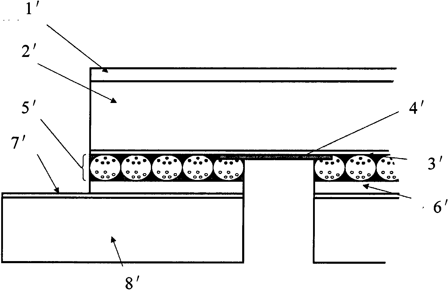
[0004] However, the texture of the electronic paper is relatively soft, and when cutting and cutting with the metal knife mold in the prior art, the cut surface of the electronic paper will be squeezed
Microscope magnification inspection shows that the edge of the cut e-paper is warped, and the edge is not flat, which makes the e-paper prone to bright spots when displayed, resulting in poor image quality, thereby reducing the product quality. Pass rate
For the front half-cut and back half-cut that require higher precision and quality requirements, this method is powerless
In addition, the metal knife mold cutting method is used, the metal knife mold must be selected, and the mold needs to be set up, and the parameters need to be adjusted during cutting, so the cost is relatively high
Furthermore, when the cutting die is a metal blade, during the process of cutting the e-paper, there will be static electricity between the metal and the e-paper, which will easily cause the electrical abnormality of the e-paper.

Method used


Image

  • Laser cutting method and equipment for electronic paper
  • Laser cutting method and equipment for electronic paper
  • Laser cutting method and equipment for electronic paper

Examples


Embodiment Construction

[0029] In order to make the technical problems, technical solutions and beneficial effects to be solved by the present invention clearer, the present invention will be further described in detail below in conjunction with the accompanying drawings and embodiments. It should be understood that the specific embodiments described here are only used to explain the present invention, not to limit the present invention.

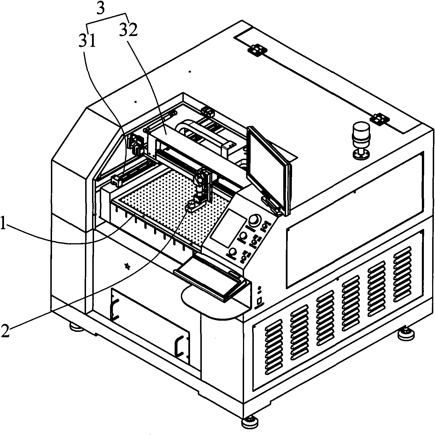
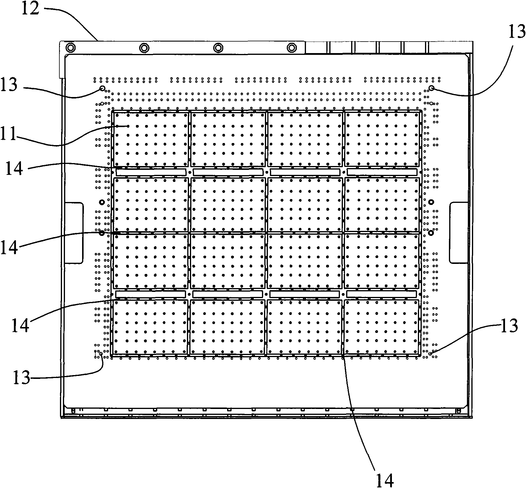
[0030] Please refer to figure 2 , is a preferred embodiment of the electronic paper laser cutting equipment of the present invention, the electronic paper laser cutting equipment includes a working platform 1 for carrying the electronic paper P, and a laser cutting head that can move vertically and horizontally relative to the working platform 1 2. A clamping system capable of clamping and positioning the electronic paper P and a control system for coordinating the actions of the above-mentioned parts. The working platform 1 is provided with a groove 14 correspond...


PUM

PropertyMeasurementUnit
Widthaaaaaaaaaa
Depthaaaaaaaaaa

Abstract

The invention discloses a laser cutting method and equipment for electronic paper. The laser cutting equipment for the electronic paper comprises a working platform used for bearing the electronic paper, a laser cutting head which can do longitudinal and lateral movement relative to the working platform, a clamping system which can clamp the electronic paper, and a control system which coordinates all the parts to act. When the electronic paper is cut, the electronic paper is placed on the working platform, clamped and positioned, the laser cutting head cuts the electronic paper under the instruction of the control system, and a ratio of the cutting power to the cutting rate is kept constant in the process of cutting. Therefore, laser cutting of the electronic paper is realized, the defect that the conventional die cutting equipment damages the internal structure of the electronic paper in the production process is overcome, the yield is improved, and the production cost is lowered. Meanwhile, semi-cutting operation can be performed on the electronic paper, and the quality of cutting complex parts such as chamfers is greatly improved.

Description

technical field [0001] The invention relates to the technical field of electronic paper processing, and more specifically, relates to a laser cutting method and equipment for electronic paper. Background technique [0002] Electronic paper (e-paper) is a display device driven by an electric field, and its display materials are mainly "electronic ink (E-ink)" and "microcapsules". Electronic ink itself is a liquid that can be printed or applied to any carrier surface. The original electronic ink is composed of very small black and white particles suspended in a transparent liquid. The microcapsule technology is to wrap electronic ink in microcapsules, thus solving the problem of aggregation of pigment particles. These capsule particles injected with electronic ink are electrically charged, the white particles are positively charged, and the black particles are negatively charged. When a negative electric field is applied on the electrode plate, the white particles with posit...

Claims


Application Information

Patent Timeline
IPC IPC(8): B23K26/00B23K26/16B23K26/42B23K37/04B23K26/08B23K26/38B23K26/402B23K26/70
Inventor 高云峰杨锦彬赵波陈夏弟李斌曾新华陈鹏
Owner HANS LASER TECH IND GRP CO LTD
Learn More