Field emission display, drive module and drive method thereof

A driving module and field emission technology, which is applied to static indicators, photometry using electrical radiation detectors, instruments, etc., and can solve the problems such as the reduction of the luminous brightness of the field emission display unit 10

Inactive Publication Date: 2011-04-20
TECO NANOTECH CO LTD
View PDF2 Cites 2 Cited by
  • Summary
  • Abstract
  • Description
  • Claims
  • Application Information

AI Technical Summary

Problems solved by technology

This means: when the same driving voltage V1 is applied at the initial time T1 and time T2, the intensity of the electron beam generated between the cathode electrode 13 an

Method used


Image

  • Field emission display, drive module and drive method thereof
  • Field emission display, drive module and drive method thereof
  • Field emission display, drive module and drive method thereof

Examples


Embodiment Construction

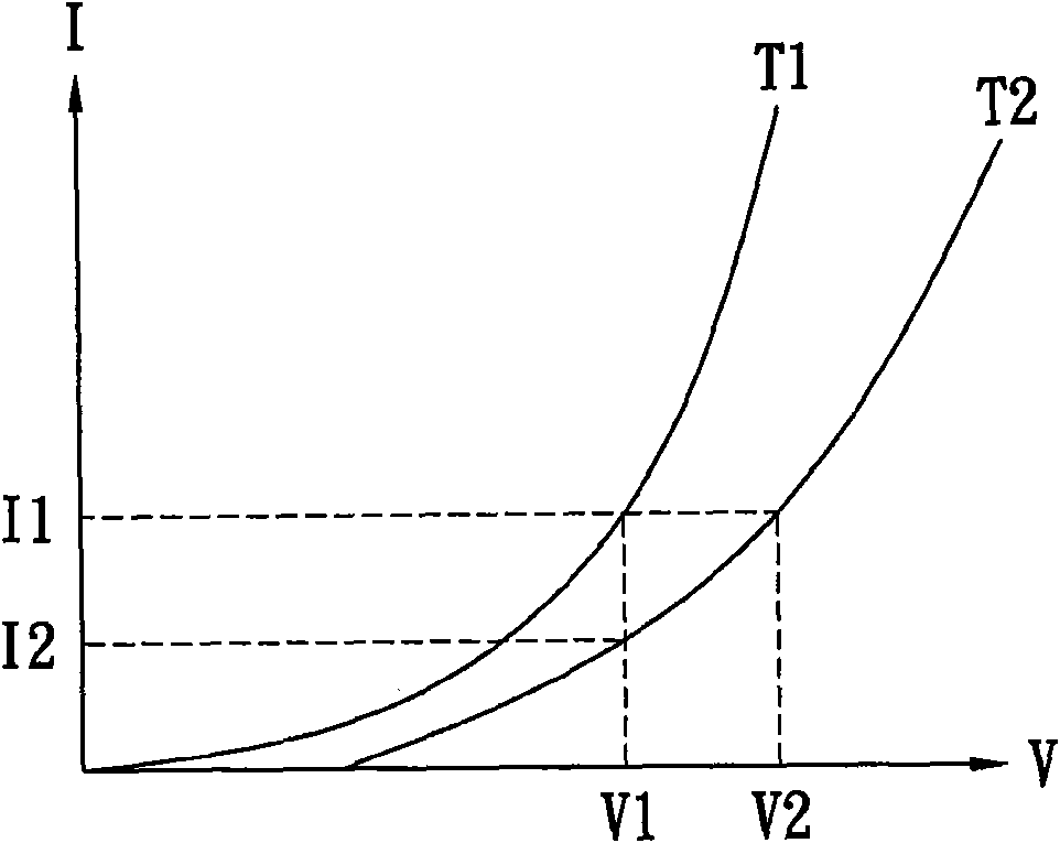
[0046] The present invention proposes a method for increasing the service life of field emission displays, only need to properly adjust the drive signal, for example: figure 2 The same driving current 11 can be obtained from the driving voltage V1 to the driving voltage V2 shown, so that the field emission display unit 10 can maintain the same luminous brightness, and the service life of the field emission display unit 10 can be greatly increased.

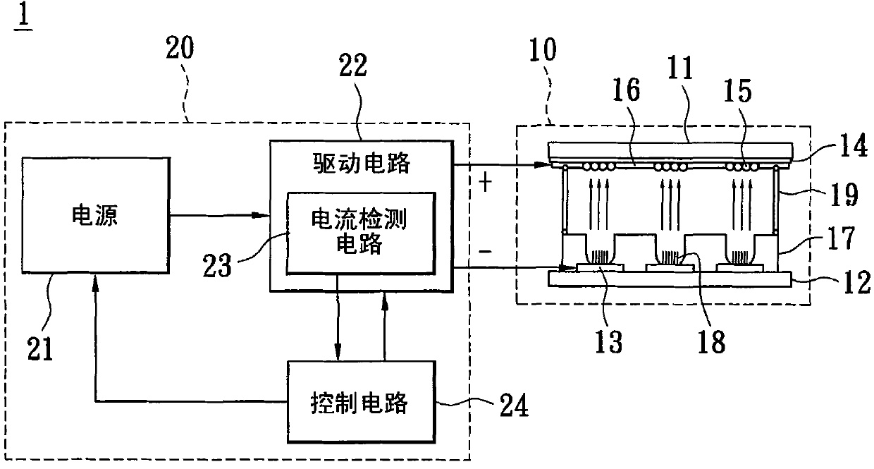
[0047] image 3 Shown is a schematic diagram of a field emission display according to an embodiment of the present invention.

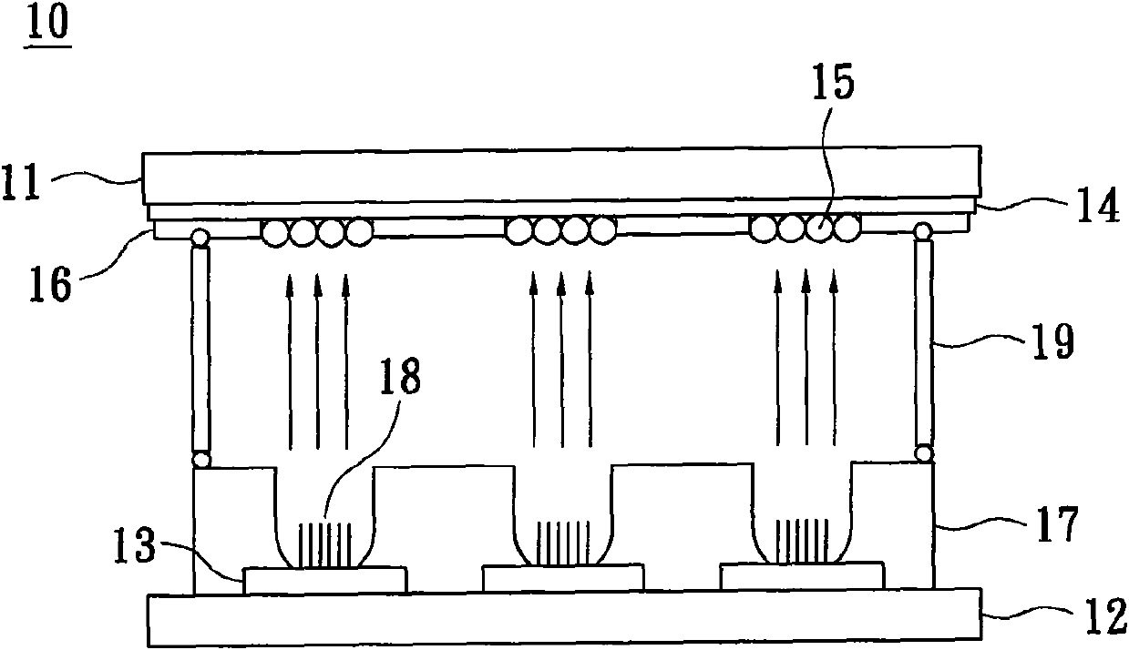
[0048] The field emission display 1 includes a field emission display unit 10 and a driving module 20 thereof. The structure of field emission display unit 10 and figure 1 Similarly, the driving module 20 includes a power supply 21 , a driving circuit 22 , a current detection circuit 23 and a control circuit 24 .

[0049] The power supply 21 is electrically connected to the driving circuit 22 , the con...


PUM


Abstract

The invention discloses a field emission display, a drive module and a drive method thereof, wherein the drive module comprises a power supply used for generating a power supply signal, a drive circuit connected with the power supply and used for generating a drive signal to be provided for a cathode electrode and an anode electrode of a field emission display unit, a current detection circuit configured in the drive circuit, and a control circuit connected with the current detection circuit, wherein the field emission display unit generates a drive current according to the drive signal; the current detection circuit is used for detecting the drive current and generating a detection signal according to the drive current; and the control circuit is used for receiving the detection signal and comparing the detection signal with a preset value and then generating a control signal for controlling the power supply or the drive circuit so as to adjust the drive signal. The invention provides the drive module with a current detection function so as to prolong the service life of the field emission display and promote the upgrade industry.

Description

technical field [0001] The invention relates to a driving module of a field emission display, in particular to a driving module of a field emission display with current detection. Background technique [0002] In recent years, with the advancement of display technology, various new-generation displays have been developed and popularized, such as: liquid crystal display (LCD), plasma display (PDP), organic electroluminescent display (OLED), field emission display (FED) )Wait. These new-generation displays, due to their advantages of flatness, light weight, thin thickness, and small size, are relatively large in size and heavy in weight compared to traditional cathode-ray tube displays. Therefore, these new-generation displays have gradually replaced traditional old models. cathode ray tube monitor (CRT). [0003] Among these new-generation displays, the field emission display has a display principle similar to that of the cathode ray tube display, which uses the emitted ele...

Claims


Application Information

Patent Timeline
IPC IPC(8): G09G3/22G01R19/165G01J1/42
Inventor 萧俊彦陈楷璿方金寿叶家福詹德凤
Owner TECO NANOTECH CO LTD
Why Eureka
Try Eureka