Fixing device and image forming apparatus
An image and fixing part technology, applied in the direction of electric recording process applying charge pattern, equipment of electric recording process applying charge pattern, electric recording technique, etc. Problems such as the difference in linear speed between the fixing nip and the correction nip, to prevent paper jams and correct the bending
- Summary
- Abstract
- Description
- Claims
- Application Information
AI Technical Summary
Problems solved by technology
Method used
Image


Examples
no. 1 approach
[0097] The following reference Figure 1 to Figure 11 , the image forming apparatus according to the first embodiment of the present invention will be described.
[0098] First, the configuration of the image forming apparatus will be described.
[0099] Such as figure 1 As shown, the image forming apparatus 1 includes: a document reading unit 2 for reading an image on a document; a paper feeding unit 4 for supplying a sheet 6a as a recording medium, and the sheet 6a is located in a plurality of stacked sheets. The uppermost sheet among the sheets 6; the image forming section 3 for forming an image read by the document reading section 2 on the sheet 6a of the paper feeding section 4; and the fixing device 10 for forming the image on the sheet 6a. The unfixed image formed in section 3 is fixed. In the image forming apparatus 1 of this embodiment, the image forming unit 3 and the paper feeding unit 4 can be separated.
[0100] The image forming unit 3 includes four image for...
no. 2 approach
[0196] The following reference Figure 12 An image forming apparatus according to a second embodiment of the present invention will be described.
[0197] The image forming apparatus of the second embodiment is substantially the same in structure as the image forming apparatus of the first embodiment. For each component, use the Figure 1 to Figure 5 The first embodiment shown will be described with the same symbols, and only the differences will be described in detail.
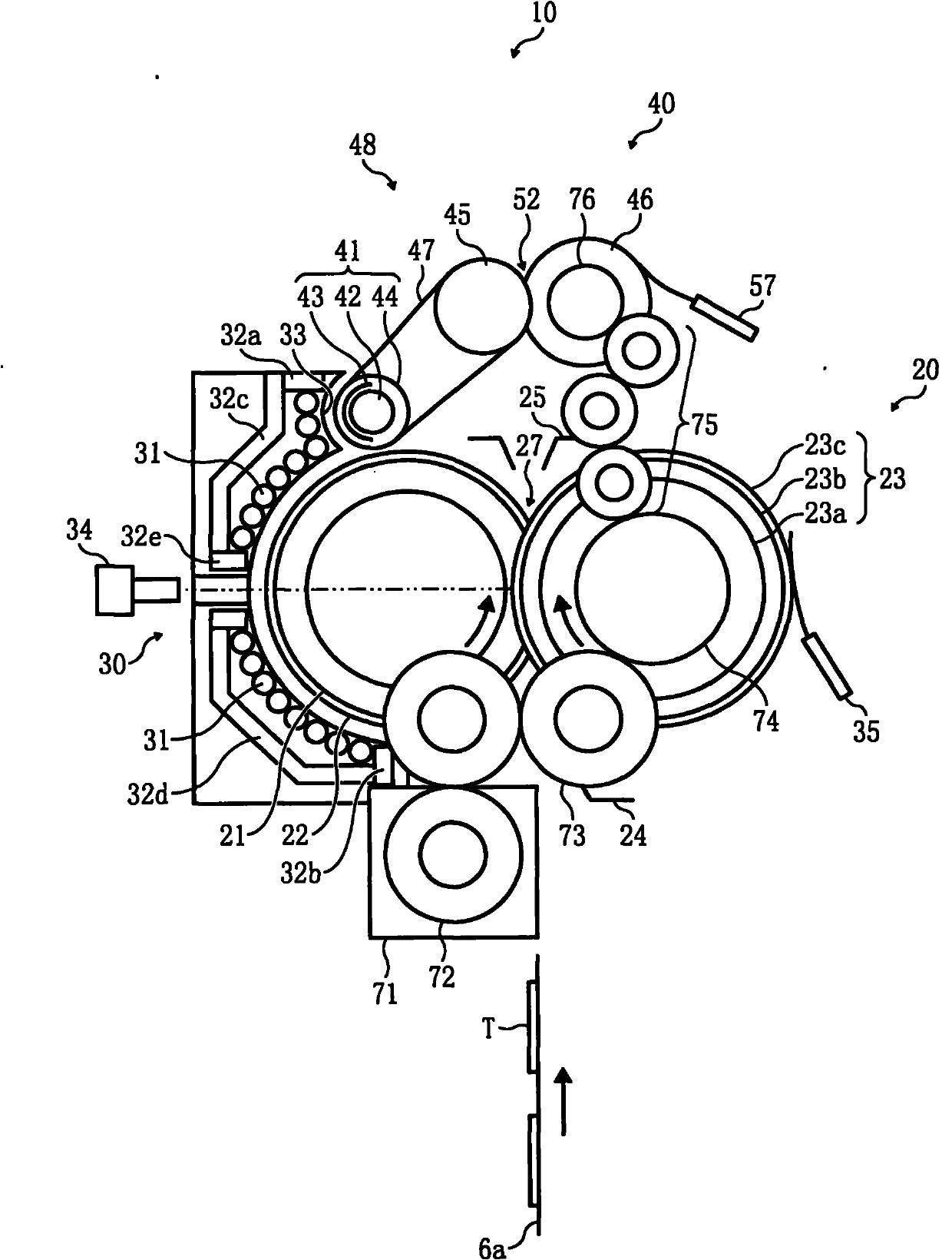
[0198] The straightening mechanism 40 includes a heating roller 41 and an elastic roller 46 contacting the heating roller 41 with pressure. A PFA layer may be formed on the surface of the heating roller 41 . Here, the heating roller 41 of this embodiment constitutes the heating roller portion 49 . Accordingly, the heating roller portion 49 can be heated by electromagnetic induction of the magnetic flux generated by the magnetic flux generating device.
[0199] The induction heating unit 30 is provided in...
no. 3 approach
[0203] see below Figure 13 An image forming apparatus according to a third embodiment of the present invention will be described.
[0204] The image forming apparatus of the third embodiment is substantially the same in structure as the image forming apparatus of the second embodiment. figure 2 The first embodiment shown will be described with the same symbols, and only the differences will be described in detail.
[0205] The core part 32 of the induction heating part 30 further has the separation core 32f in addition to side core 32a, 32b, center core 32e, arch core 32c, 32d. The separation core 32 f is provided in the vicinity of an intermediate surface between the fixing sleeve 22 and the heating roller 41 . The split core 32 f protrudes toward the coil guide 33 to separate a portion of the excitation coil 31 near the fixing sleeve 22 from a portion near the heating roller 41 . The separation core 32f of this embodiment constitutes the protruding member of the present...
PUM
 Abstract
Description
Claims
Application Information
 - R&D
- Intellectual Property
- Life Sciences
- Materials
- Tech Scout
- Unparalleled Data Quality
- Higher Quality Content
- 60% Fewer Hallucinations
Browse by: Latest US Patents, China's latest patents, Technical Efficacy Thesaurus, Application Domain, Technology Topic, Popular Technical Reports.
© 2025 PatSnap. All rights reserved.Legal|Privacy policy|Modern Slavery Act Transparency Statement|Sitemap|About US| Contact US: help@patsnap.com