
Thin film forming method and film forming apparatus

A film-forming device and thin-film technology, which is applied in the direction of ion implantation plating, metal material coating process, coating, etc., can solve the problem that the thin film cannot be manufactured according to the design, and achieve the effect of cheap device cost

Inactive Publication Date: 2011-04-13
PANASONIC CORP
View PDF5 Cites 3 Cited by
  • Summary
  • Abstract
  • Description
  • Claims
  • Application Information

AI Technical Summary

Problems solved by technology

Films cannot be fabricated as designed when the film-forming area varies

Method used


Image

  • Thin film forming method and film forming apparatus
  • Thin film forming method and film forming apparatus
  • Thin film forming method and film forming apparatus

Examples


Embodiment Construction

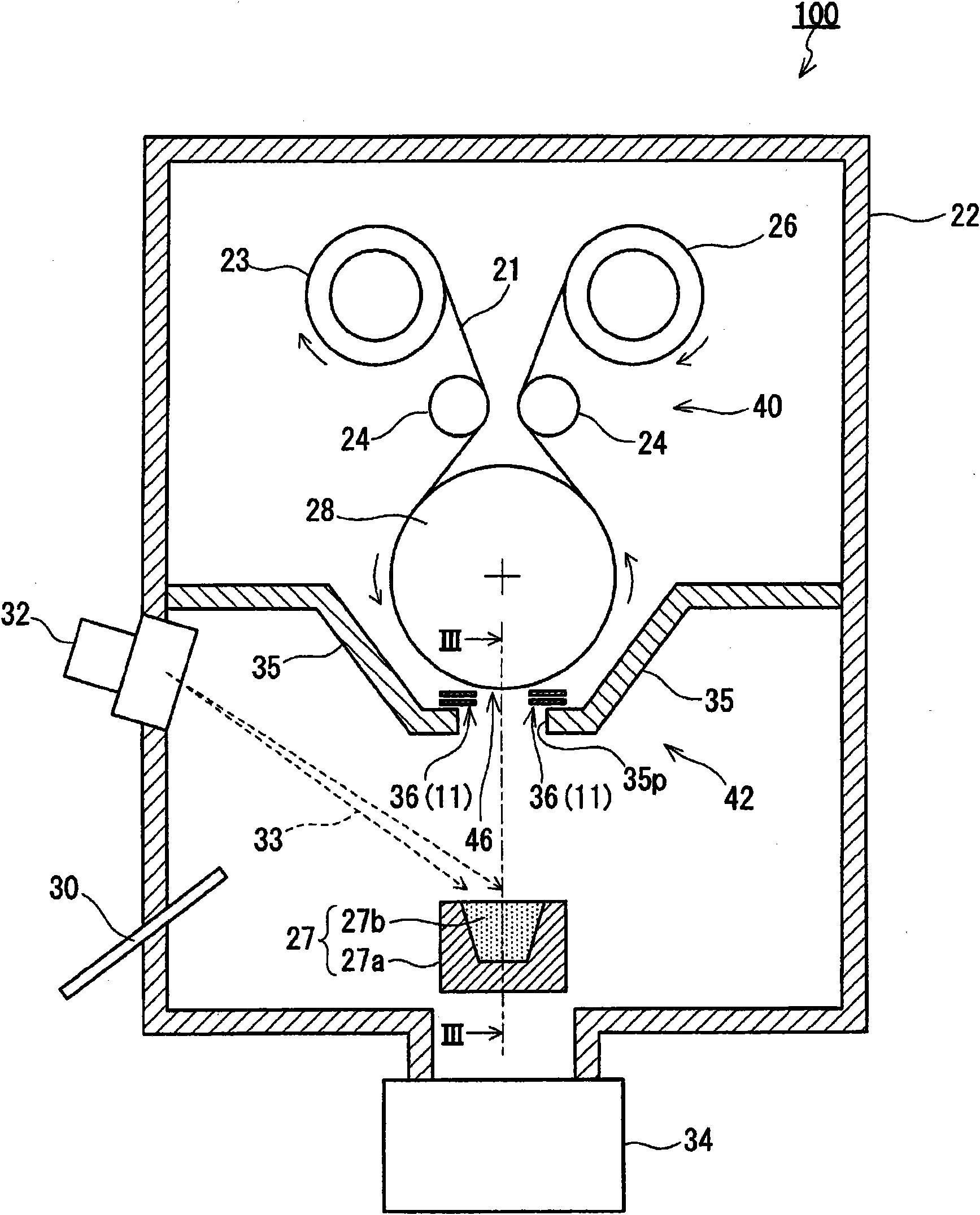
[0031] Hereinafter, an embodiment of the present invention will be described with reference to the drawings. like figure 1 As shown, the film forming apparatus 100 of this embodiment has a vacuum chamber 22 , a substrate transfer unit 40 , a shielding unit 42 and a film forming source 27 . The substrate transfer unit 40 , the mask unit 42 and the film forming source 27 are arranged in the vacuum chamber 22 . A vacuum pump 34 is connected to the vacuum tank 22 . An electron gun 32 and a source gas introduction pipe 30 are provided on the side wall of the vacuum chamber 22 .

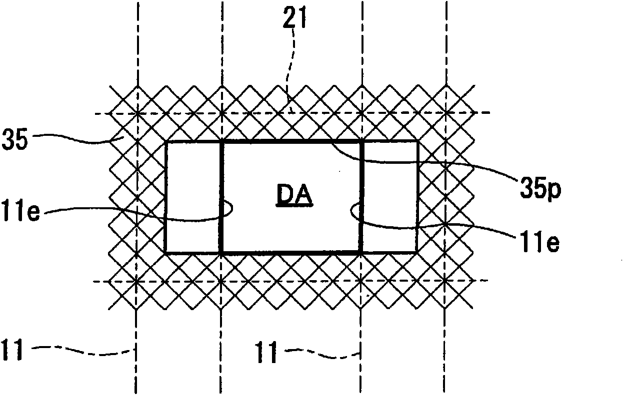
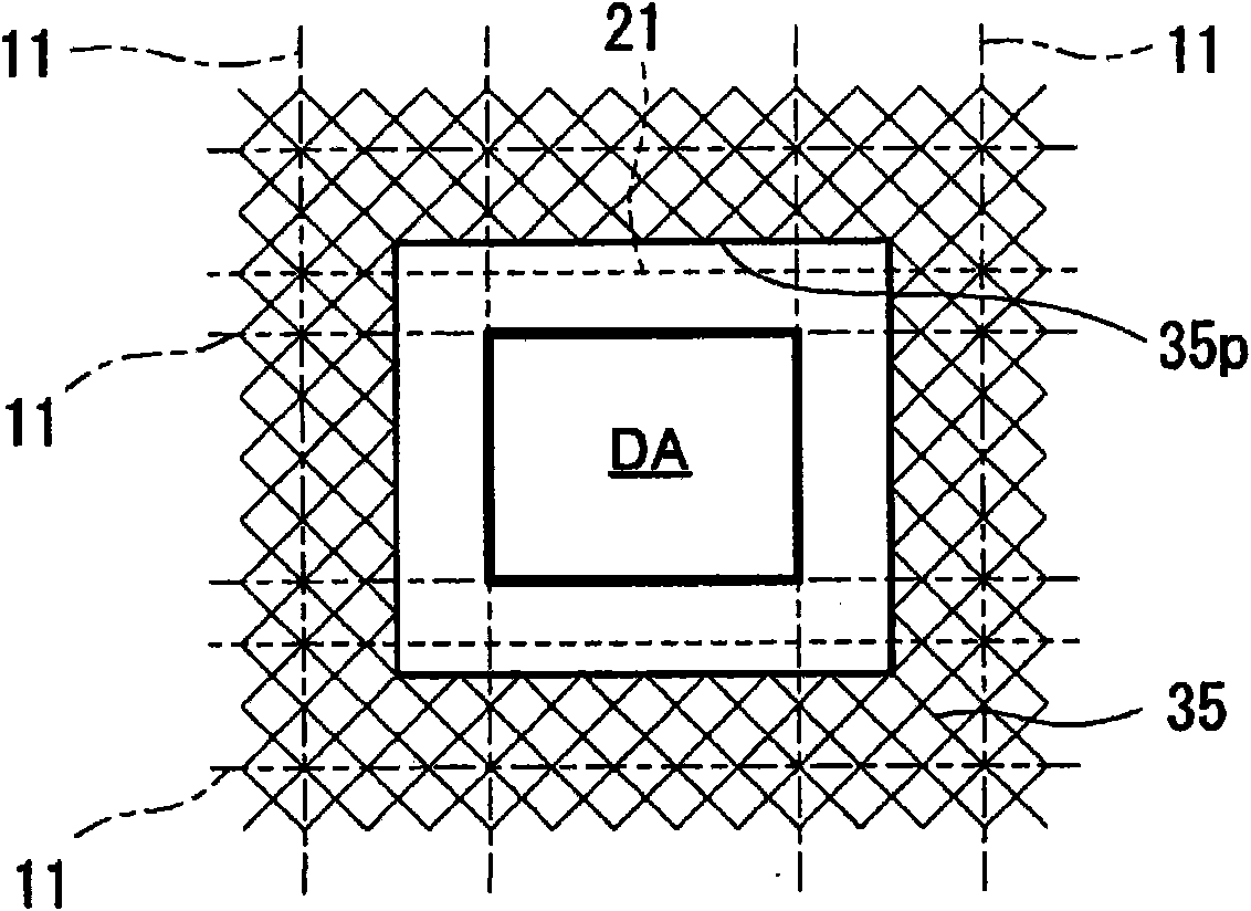
[0032] The shielding unit 42 is provided between the film forming source 27 and the substrate conveying unit 40 in such a manner as to limit the film forming region on the surface of the substrate 21 . The shielding unit 42 is composed of a fixed shielding plate 35 and a movable shielding mechanism 36 .

[0033] The fixed shielding plate 35 is installed in the vacuum chamber 22 . The fixed shielding p...


PUM

PropertyMeasurementUnit
thicknessaaaaaaaaaa

Abstract

Provided is a method for forming a thin film by depositing on a substrate (21) particles sputtered in vacuum from a film forming source (27). Specifically, the particles are deposited on the substrate (21) in a state where a movable endless strip (11) is arranged between the film forming source (27) and the substrate (21) so that a film forming region (DA) is defined on a surface of the substrate (21) by the movable endless strip (11) of which the approach route and the return route are set between the film forming source (27) and the substrate (21). The substrate (21) is typically a long substrate having flexibility. The particles are deposited on the substrate (21) while the substrate is being transferred from a feeding roller (23) to a take-up roller (26).

Description

technical field [0001] The invention relates to a thin film forming method and a film forming device. Background technique [0002] Currently, thin-film technologies are being widely developed to support higher performance and miniaturization of equipment. The thin film of equipment not only brings direct advantages to users, but also plays an important role from the environmental point of view such as the protection of earth resources and the reduction of power consumption. [0003] Generally, in vacuum film formation, a film formation source is opposed to a substrate, and a film formation region on the surface of the substrate is defined by a mask. There is also a technique of depositing on the substrate only the particles incident on the substrate at a specific angle range among the particles flying from the film formation source. [0004] In order to increase the productivity of the thin film, a long-time film-forming technique is necessary. In order to achieve long-t...

Claims


Application Information

Patent Timeline
Patent Type & Authority Applications(China)
IPC IPC(8): C23C14/00C23C14/24
CPCC23C14/042C23C14/30C23C14/562
Inventor 本田和义神山游马筱川泰治山本昌裕
Owner PANASONIC CORP
Learn More