Lead crimping device
A wire crimping and hydraulic technology, applied in the direction of connection, circuit/collector parts, electrical components, etc., can solve the problem of labor and labor, and achieve the effect of flexible and light use, shortened operation time and low cost.
- Summary
- Abstract
- Description
- Claims
- Application Information
AI Technical Summary
Problems solved by technology
Method used
Image
Examples
Embodiment Construction
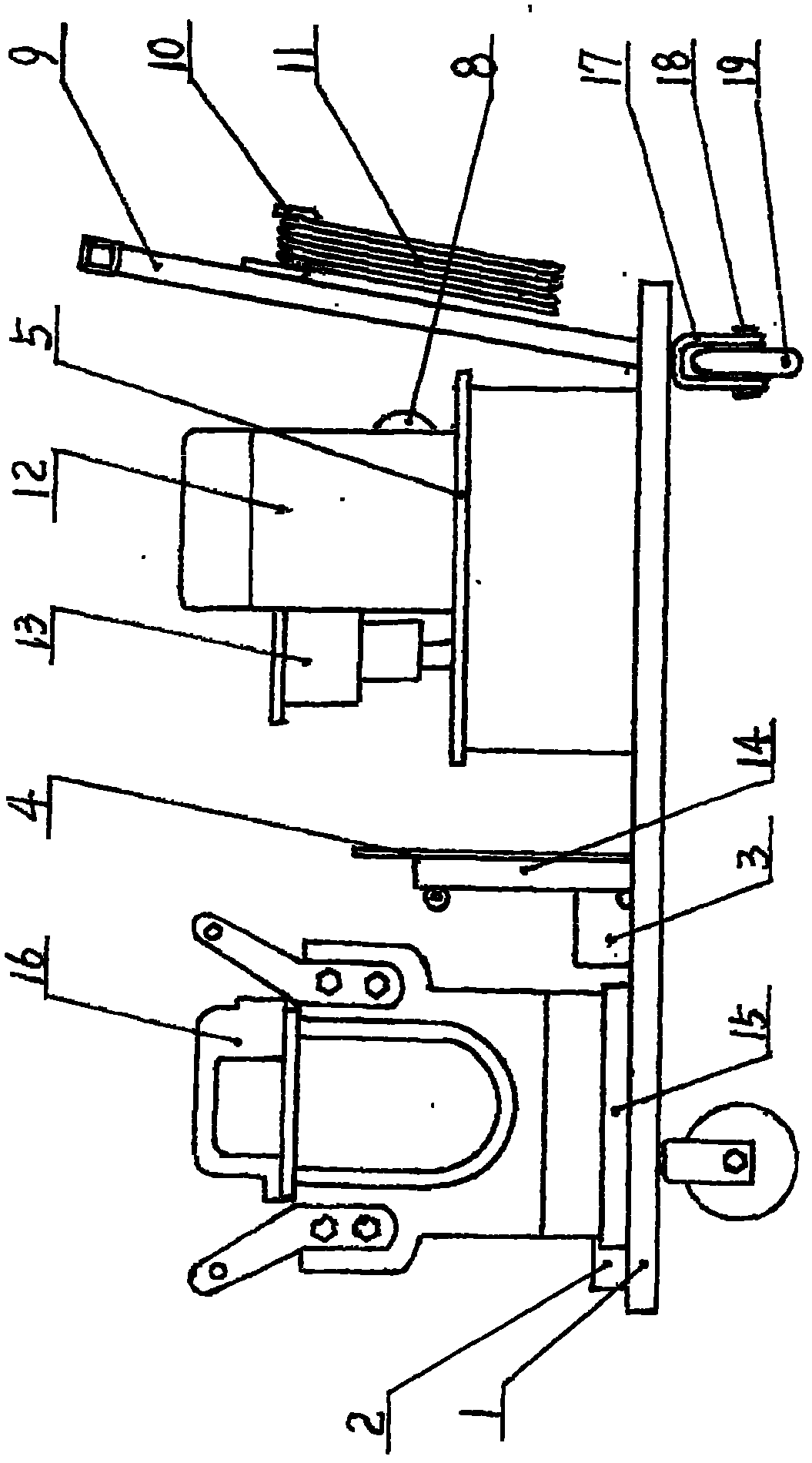
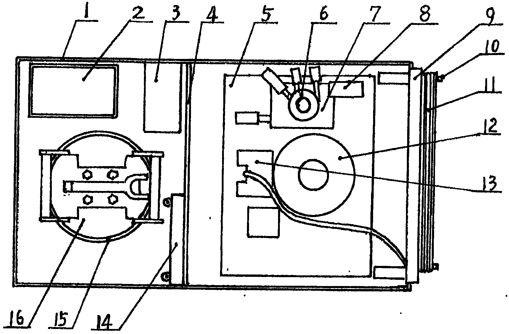
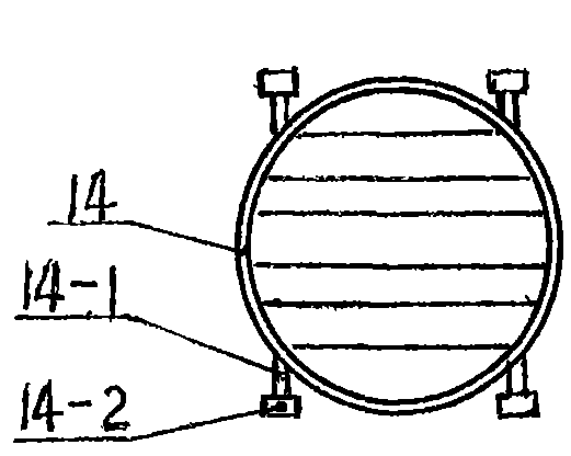
[0011] Examples, see attached Figure 1~3 , the car body of the wire crimping device is a rectangular body with an edge, there is no fixed push handle 9 at the right end of the car body 1, and a cable hook 10 is fixed outside the two vertical frames of the push handle 9, and the cable is hung on the hook 10. Line 11. A partition 4 is set in the middle of the car body 1, the right side of the partition 4 is fixed with a motor seat 5, the motor 12 and the valve seat 7 are fixed above the motor seat 5, and the valve 6 and the pressure gauge 8 are installed on the valve seat 7, and the motor 12 Motor switch 13 is installed on the left side. A movable hydraulic top seat 14 is placed in the middle of the left side of the dividing plate 4, and two hydraulic top seat shafts 14-1 are fixed below the hydraulic top seat 14, and top seat wheels 14-1 are mounted on both sides of the hydraulic top seat shaft 14-1. 2. After the mobile hydraulic top seat 14 is taken down, the hydraulic top ...
PUM
 Abstract
Description
Claims
Application Information
 - Generate Ideas
- Intellectual Property
- Life Sciences
- Materials
- Tech Scout
- Unparalleled Data Quality
- Higher Quality Content
- 60% Fewer Hallucinations
Browse by: Latest US Patents, China's latest patents, Technical Efficacy Thesaurus, Application Domain, Technology Topic, Popular Technical Reports.
© 2025 PatSnap. All rights reserved.Legal|Privacy policy|Modern Slavery Act Transparency Statement|Sitemap|About US| Contact US: help@patsnap.com


