
Novel adjustable integrated optical power splitter

An optical power splitter, a new type of technology, applied in the coupling of optical waveguides and other directions, can solve the problems of different optical signal losses, inability to guarantee communication terminals, easy to be affected by environmental factors such as stress, etc., to achieve the advantages of realization, ease of operation, Reliable splitting ratio adjustable effect

Inactive Publication Date: 2011-04-13
HANGZHOU TIANYE COMM EQUIP
View PDF0 Cites 1 Cited by
  • Summary
  • Abstract
  • Description
  • Claims
  • Application Information

AI Technical Summary

Problems solved by technology

[0002] For a long time, due to the limitation of one-time forming process of integrated optical waveguide, it is difficult for integrated optical power splitter to realize the function of adjustable optical power distribution, which restricts the realization of flexible distribution of optical power according to different link losses in the construction of optical network structure
At present, there are two technical ways to obtain practical adjustable optical power splitters: one is the Y-shaped optical fiber fusion tapered optical power adjustable coupler, by putting two bare optical fibers together and heating them in a high-temperature flame Make it melt, and stretch the fiber at both ends of the fiber at the same time, so that the melting zone of the fiber becomes a tapered transition section to form a coupler. This method is easy to implement in technology, but due to the large size of the device and its vulnerability to environmental factors such as stress Influence, can not provide a stable optical power distribution ratio; the other is to use the electro-optic or thermo-optic effect, by adding electrodes or thermal electrodes next to the waveguide to change the refractive index of one of the branch waveguides to achieve adjustable Optical energy distribution, but due to the high process requirements for making electrodes, it also greatly increases the cost of equipment
[0003] In actual fiber optic network deployment, often due to the different distances between communication terminals (Optical Network Unit, ONU) and backbone network nodes, the loss of optical signals on different links is different, so it cannot guarantee that each communication terminal (Optical Network Unit, ONU) ) to receive the same optical power

Method used


Image

  • Novel adjustable integrated optical power splitter
  • Novel adjustable integrated optical power splitter
  • Novel adjustable integrated optical power splitter

Examples


Embodiment 1

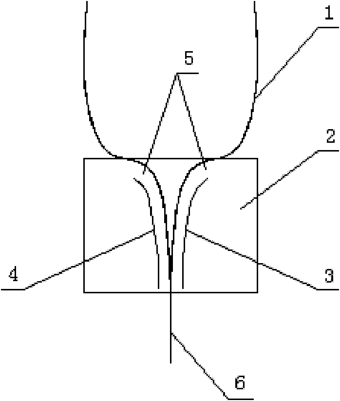
[0015] Such as figure 1 As shown, a novel adjustable integrated optical power splitter provided in this embodiment includes a Y-branch waveguide 1 and a coupling region 2, and an additional waveguide I3 and an additional waveguide II4 are provided in the coupling region 2, and the additional waveguide I3 and The additional waveguide II4 is parallel to the coupling area 2 and symmetrically distributed on both sides 5 of the Y-branch waveguide 1 , and the coupling area 2 is set at the total branch waveguide end 6 of the Y-branch waveguide 1 .

[0016] In order to change the equivalent refractive index of the coupling region by injecting materials with different refractive indices, the two output light energies can be adjusted between 5% and 85% of the input light energy, while ensuring that the overall light energy loss can be controlled at 10%. Hereinafter, the additional waveguide I3 and the additional waveguide II4 are grooves.

[0017] Laser path: The laser source emits a b...


PUM


Abstract

The invention discloses a novel adjustable integrated optical power splitter. The novel adjustable integrated optical power splitter comprises a Y-branch waveguide and a coupled zone, wherein an additional waveguide I and an additional waveguide II are arranged in the coupled zone, are parallel to the coupled zone and are symmetrically distributed on two sides of the Y-branch waveguide at the same time; and the coupled zone is arranged at the total branch waveguide end of the Y-branch waveguide. The novel adjustable integrated optical power splitter conveniently and reliably realizes adjustability of a splitting ratio of the optical power splitter by filling materials with different refractive indexes into a groove and changing the effective refractive index of the coupled zone by using the additional waveguides I and II, and has the great advantages that: an integrated photolithographic process is realized and the optical power splitter is easy to operate.

Description

technical field [0001] The invention relates to an integrated optical power splitter, in particular to a novel adjustable integrated optical power splitter with adjustable primary splitting ratio. Background technique [0002] For a long time, due to the limitation of one-time molding process of integrated optical waveguide, it is difficult to realize the adjustable optical power distribution function of integrated optical power splitter, which restricts the realization of flexible optical power distribution according to different link losses in the establishment of optical network structure. At present, there are two technical ways to obtain practical adjustable optical power splitters: one is the Y-shaped optical fiber fusion tapered optical power adjustable coupler, by putting two bare optical fibers together and heating them in a high-temperature flame Make it melt, and stretch the fiber at both ends of the fiber at the same time, so that the melting zone of the fiber be...

Claims


Application Information

Patent Timeline
Patent Type & Authority Applications(China)
IPC IPC(8): G02B6/28
Inventor 刘勇尹爽符建
Owner HANGZHOU TIANYE COMM EQUIP
Learn More