Straight-shaft engine

An engine and direct shaft technology, applied in the direction of combustion engines, machines/engines, mechanical equipment, etc., can solve the problems of affecting work, the maximum force is not optimally utilized, etc., to reduce friction, simple structure, and conducive to popularization and application Effect

Inactive Publication Date: 2011-04-13
孔璐
View PDF4 Cites 3 Cited by
  • Summary
  • Abstract
  • Description
  • Claims
  • Application Information

AI Technical Summary

Problems solved by technology

[0002] At present, the engines on the market are generally crankshaft engines. The crankshaft engine uses the working principle of four strokes. Three strokes assist one stroke to do work. In the third stroke, the piston moves downward in a straight line to do work, which is transferred to the crankshaft by the piston connecting arm and converted into rotational motion. At this time, when the piston is at the top dead center position and the crankshaft is at the top dead center, the maximum force of the combustion chamber at the moment of explosion is not optimally utilized, which affects the effective performance of work

Method used


Image

  • Straight-shaft engine
  • Straight-shaft engine
  • Straight-shaft engine

Examples


Embodiment Construction

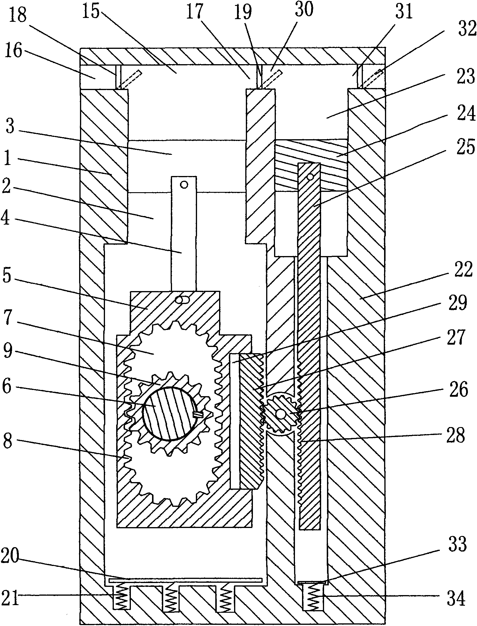
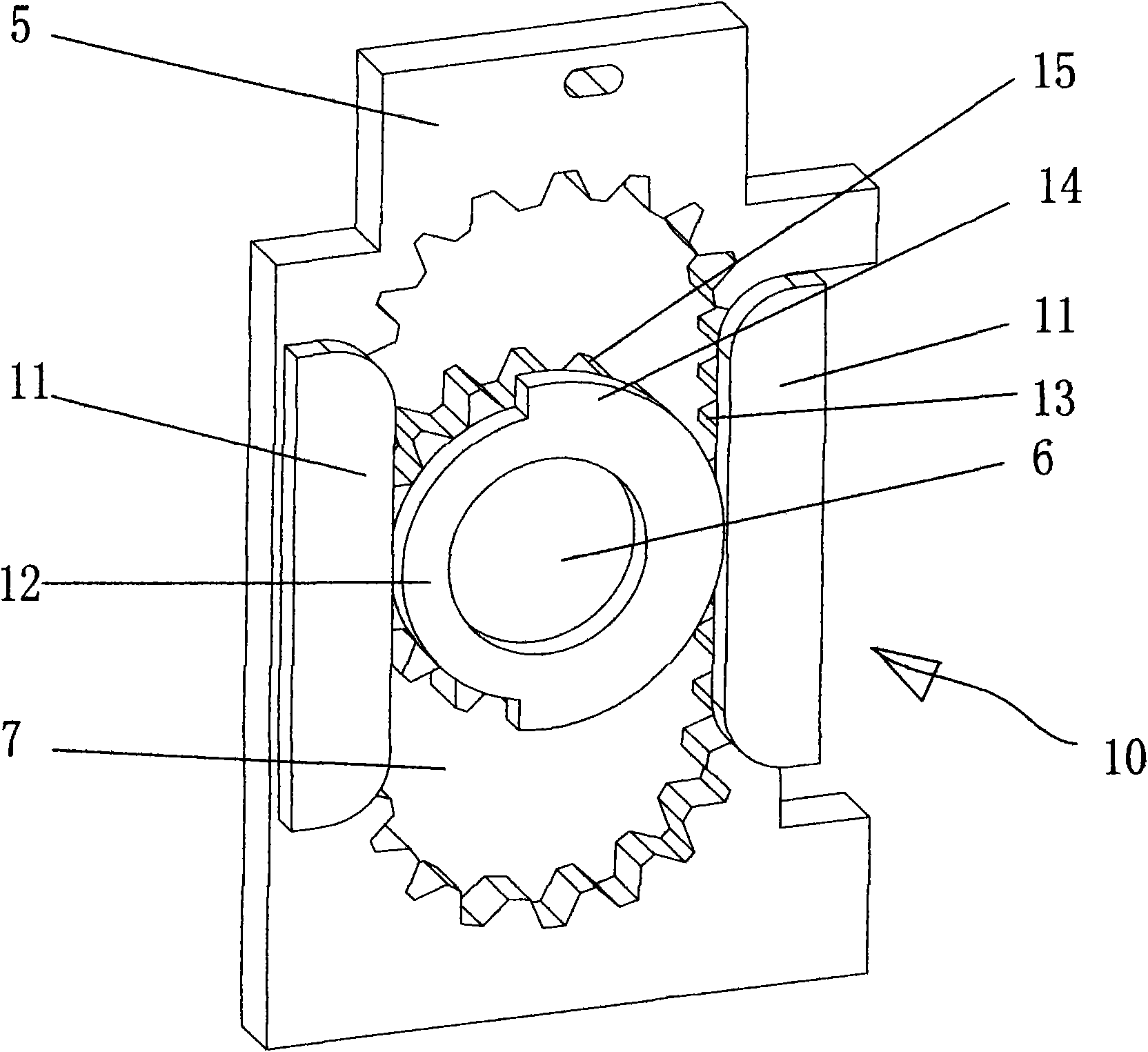
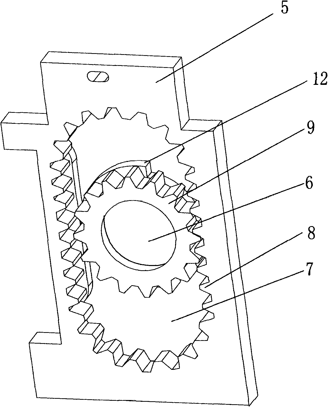
[0022] Such as figure 1 , figure 2 As shown, a direct shaft engine is characterized in that it includes a main work cylinder 1, and the main work cylinder 1 includes a cavity 2, and a main work piston 3, a connecting rod 4, and a clutch inner tooth are arranged in the cavity 2 Assembly 5 and transmission straight shaft 6, one end of the connecting rod 4 is fixed to the main work piston 3, and the other end is connected to the clutch internal tooth assembly 5 which can move left and right; the middle part of the clutch internal tooth assembly 5 is provided with a long strip Slot 7, the inner side of the elongated groove 7 is provided with an inner gear ring 8; The meshed gear 9; and a clutch mechanism 10 that makes the gear 9 and the inner gear ring 8 unidirectionally rotate.

[0023] In this embodiment, the clutch mechanism 10 includes left and right clutch baffles 11 arranged on the clutch internal tooth assembly 5 and a clutch ring 12 fixed on the gear 9; the left and rig...


PUM


Abstract

The invention relates to a straight-shaft engine. The straight-shaft engine is characterized by comprising a main work cylinder, wherein the main work cylinder comprises a cavity; a main work piston, a connecting rod, a clutch internal tooth assembly and a transmission straight shaft passing through a gear are arranged in the cavity; a strip groove is formed on the middle part of the clutch internal tooth assembly; an internal tooth ring is arranged on the inside edge of the strip groove; the transmission straight shaft passes through the gear and the strip groove; a gear meshed with the single edge of the internal tooth ring is arranged on the transmission straight shaft; and a clutch mechanism for allowing the gear and the internal tooth ring to make unidirectional circulating rotation is arranged on the transmission straight shaft. The straight-shaft engine has the advantages that: 1, by the matching motion of the clutch internal tooth assembly and the gear, a straight shaft is driven to make unidirectional rotation, and the complex energy conversion mode of a crankshaft is changed, so the friction force is reduced and the effective power is improved; 2, an work assisting cylinder is arranged, so that the piston of the main work cylinder compresses exhaust gas upwards to push a piston of the work assisting cylinder to assist in applying work downwards, and the straight-shaft engine is favorable for energy conservation and emission reduction; and 3, the straight-shaft engine has a simple structure, reduces the cost of manufacturing the engine, and is favorable for popularization and application.

Description

【Technical field】 [0001] The present invention relates to an engine, and more particularly to a direct shaft engine. 【Background technique】 [0002] At present, the engines on the market are generally crankshaft engines. The crankshaft engine uses the working principle of four strokes. Three strokes assist one stroke to do work. In the third stroke, the piston moves downward in a straight line to do work, which is transferred to the crankshaft by the piston connecting arm and converted into rotational motion. At this time, when the piston is at the top dead center position and the crankshaft is at the top dead center, the maximum force of the combustion chamber at the moment of explosion has not been optimally utilized, which affects the effective performance of work. Moreover, the utilization of waste gas is a subject that people have been trying to solve but has not been able to solve well. If the waste gas can be used to assist work, it will be more conducive to energy sa...

Claims


Application Information

Patent Timeline
IPC IPC(8): F02B75/40F02B41/06
Inventor 孔璐孔建新孔建勇
Owner 孔璐
Why Eureka
Try Eureka