
Knitting needle and needle plate component of computerized flat knitter

A computerized flat knitting machine and knitting needle technology, which is applied to textiles and papermaking, knitting, weft knitting, etc. It can solve the problems of knitting needle error, complex structure, increased weight of machine head and machine, etc., so that it is not easy to crash and the movement is stable. Reliable, weight-saving effect

Inactive Publication Date: 2011-04-13
CHANGZHOU DEBEI MACHINERY
View PDF6 Cites 1 Cited by
  • Summary
  • Abstract
  • Description
  • Claims
  • Application Information

AI Technical Summary

Problems solved by technology

[0006] The connection of knitting needles and connecting pins such as Figure 10 As shown, the movement of the knitting needle is realized by the mountain plate mechanism (not marked on the picture) driving the needle clock of the connecting pin, not directly driving the needle clock of the knitting needle, because there is a certain gap between the knitting needle and the connecting pin to ensure the connection The stitch can rotate around the connection point, and this gap will cause errors in the forward and backward movement of the knitting needle; at the same time, the structure of the knitting needle and the connecting stitch leads to a complicated structure from the needle hook to the needle bell; the height and position control of the spring stitch needle bell The working state of the knitting needles, which also determines the machine head ("mountain mechanism") that drives the knitting needles and stitches, needs to increase the mechanism that controls the height of the needle bell of the spring stitches, which eventually leads to an increase in the weight of the machine head and the machine

Method used


Image

  • Knitting needle and needle plate component of computerized flat knitter
  • Knitting needle and needle plate component of computerized flat knitter
  • Knitting needle and needle plate component of computerized flat knitter

Examples


Embodiment Construction

[0020] The invention will be described in further detail below in conjunction with the accompanying drawings and embodiments.

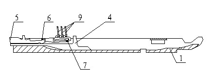
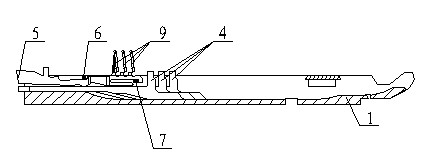
[0021] Such as Figure 1~9 As shown, a knitting needle and needle board assembly of a computerized flat knitting machine includes a needle board 1, a knitting needle 2, and a needle selection pin 5, and also includes a selection pin 4, a first steel wire 6, a second steel wire 7, and a needle selection jack 9 , Lower stitch 3 and needle gauge 8, the lower stitch 3 is installed in the groove below the needle plate 1, the knitting needle 2 is placed on the lower stitch 3, and connected with the lower stitch 3 through the groove under the needle clock, select the stitch 4 is installed behind the lower pin 3, the needle selection pin 5 is installed above the selection pin 4, the first steel wire 6 and the second steel wire 7 are both against the needle selection pin 5, and the needle selection piece 9 is pressed on the needle selection pin 5 .

[0022] ...


PUM


Abstract

The invention relates to a knitting needle and needle plate component of a computerized flat knitter. The component comprises a needle plate (1), a knitting needle (2) and a needle selection stitch (5), as well as a selection stitch (4), a first steel wire (6), a second steel wire (7), a needle selection sheet (9), a lower stitch (3) and a needle gauge (8), wherein the lower stitch (3) is mounted in a groove below the needle plate (1), the knitting needle (2) is placed on the upper surface of the lower stitch (3) and connected with the lower stitch (3) through the groove below a butt of the knitting needle, the selection stitch (4) is mounted behind the lower stitch (3), the needle selection stitch (5) is mounted above the selection switch (4), the first steel wire (6) and the second steel wire (7) props against the needle selection stitch (5), and the needle selection sheet (9) is pressed on the needle selection stitch (5). The knitting needle and needle plate component can carry out needle selection automatically, and the knitting needle can work smoothly and reliably during high-speed motion, thereby improving the working efficiency of a machine and ensure the quality of fabrics.

Description

technical field [0001] The invention relates to a knitting needle and needle plate assembly of a computerized flat knitting machine. Applied to computerized flat knitting machines. It belongs to the field of knitting machines. Background technique [0002] The computerized flat knitting machine belongs to the weft knitting machine in the knitting machine. It is a common processing equipment for processing woolen sweaters and cashmere sweaters; key executive components of the institution. [0003] The knitting needle and needle board assembly are the key components of the computerized flat knitting machine. Its working principle and structure determine the working principle and structural size of the machine head (including the "mountain mechanism") that drives the knitting needle assembly, thus determining and affecting the computer The overall performance and structural size of the flat knitting machine. [0004] At present, some knitting needles and needle board compo...

Claims


Application Information

Patent Timeline
IPC IPC(8): D04B15/00
Inventor 陶惠昌贝尼特施涛伯蔡尼
Owner CHANGZHOU DEBEI MACHINERY
Learn More