
Electric stepless speed changer with three-gear speed change function and power drive mode thereof

A continuously variable transmission and three-speed transmission technology, which is applied to the arrangement of multiple different prime movers of the air pressure power device and the general power device, and the power device, etc., can solve the limitation of the speed adjustment range of the electric continuously variable transmission, the influence of the engine, Waste and other problems, to achieve the effect of expanding the range of transmission ratio, improving power density and reducing volume

Active Publication Date: 2011-04-13
YANCHENG BUGAO AUTO PARTS MFG CO LTD
View PDF9 Cites 27 Cited by
  • Summary
  • Abstract
  • Description
  • Claims
  • Application Information

AI Technical Summary

Problems solved by technology

[0003] However, the electric continuously variable transmission also has certain defects: First, compared with the mechanical or hydraulic transmission, it can achieve a larger speed regulation range in a relatively compact space. Due to the limitation of the space size, the electric continuously variable transmission The range of speed regulation is also limited; secondly, the input shaft of the electric continuously variable speed is generally fixedly connected with the engine shaft. When only the motor is used to drive the car alone or the motor generates power to recover the kinetic energy during braking, the motor will drive the engine to idle, causing waste and affecting the engine
Patent No. 200710121112.2, the name is "an electric continuously variable transmission" through a set of planetary gear structure and the patent number is 200710074741.4, the name is "hybrid electric vehicle powertrain". Although the fixed connection between the engine and the electric continuously variable transmission is solved through the clutch problem, but it does not expand the gear ratio range of the electric continuously variable transmission

Method used


Image

  • Electric stepless speed changer with three-gear speed change function and power drive mode thereof
  • Electric stepless speed changer with three-gear speed change function and power drive mode thereof
  • Electric stepless speed changer with three-gear speed change function and power drive mode thereof

Examples


Embodiment Construction

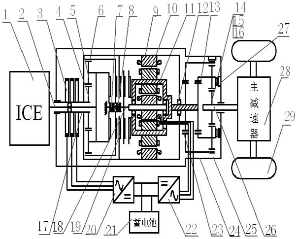
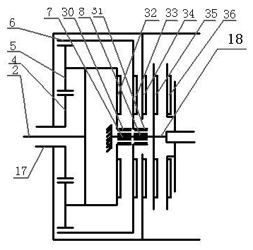
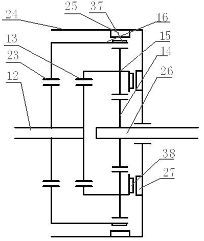
[0017] Such as figure 1 As shown, the electric continuously variable transmission of the present invention mainly includes a powertrain housing 24, a double-rotor motor and two sets of planetary gear mechanisms, and the double-rotor motor and two sets of planetary gear mechanisms are all arranged in the powertrain housing 24, wherein , the double-rotor motor is arranged between two sets of planetary gear mechanisms. The first set of planetary gear mechanism realizes the switching of the vehicle among various driving modes, and the second set of planetary gear mechanism realizes the three-speed transmission. The first set of planetary gear mechanism is connected to the engine 1 through the engine output shaft 2 , the second set of planetary gear mechanism is connected to the final drive 28 through its output shaft sun gear shaft 26 , and the final drive 28 controls the wheels 29 .

[0018] The double-rotor motor is a three-layer structure arranged concentrically. The outermost...


PUM


Abstract

The invention discloses an electric stepless speed changer with three-gear speed change function for transport vehicles, and a power drive mode thereof. The speed changer comprises a dual-rotor motor and two groups of planetary gear mechanisms, wherein a first group of planetary gear mechanism is connected with an engine through an output shaft of the engine; a second group of planetary gear mechanism is connected with a main speed reducer through a sun wheel shaft; the dual-rotor motor is arranged between the two groups of planetary gear mechanisms and has a coaxial three-layer structure; and the first group of planetary gear mechanism switches a pure electric drive mode, a full-hybrid drive mode and a parallel hybrid drive mode, and the second group of planetary gear mechanism changes transmission ratio, so that the transmission ratio range is expanded, the volume of the dual-rotor motor is reduced, power density is improved, and energy during braking is recovered.

Description

technical field [0001] The invention belongs to the technical field of automobile AC motors and their control, and in particular relates to an electric continuously variable transmission with double rotors, which is applied to road transport vehicles. Background technique [0002] In order to keep the internal combustion engine ICE running at the best efficiency in the whole operating condition and reduce the complexity of the device, a dual-rotor motor is used. The dual-rotor motor is composed of three main parts: the inner rotor, the outer rotor and the stator. The three main parts can form two radially arranged motors, wherein the inner rotor and the outer rotor form the inner motor, and the outer rotor and the stator form the outer motor. Generally, the inner rotor is connected to the output shaft of the engine, and the outer rotor is connected to the shaft of the final drive, forming an electric continuously variable transmission EVT. Using electric drive to control th...

Claims


Application Information

Patent Timeline
IPC IPC(8): B60K6/543H02K7/14H02K7/18
CPCY02T10/92
Inventor 何仁梁琳琳
Owner YANCHENG BUGAO AUTO PARTS MFG CO LTD
Learn More