Thrust rod assembly

A thrust rod and assembly technology, which is applied in the field of parts and components, can solve the problems of rubber body rupture, uneven force, life discount of thrust rod, etc., and achieve the goal of prolonging service life, increasing load force, ensuring stability and reliability Effect

Inactive Publication Date: 2011-04-13
十堰市润莱机电制造有限公司
View PDF7 Cites 2 Cited by
  • Summary
  • Abstract
  • Description
  • Claims
  • Application Information

AI Technical Summary

Problems solved by technology

[0003] With the above scheme, the rubber bearings on the rod heads at both ends are prone to rupture of the rubber body. The reason is that the displacement of the rubber body in the rod head is relatively small and the load is too large (>400000 at the maximum) when it is subjected to an instantaneous impact force. Niu), the rubber material of the rubber body is too small, and the force is uneven (the force volume accounts for about 30%), resulting in a greatly reduced life of the thrust rod, thereby affecting the performance of the vehicle

Method used


Image

  • Thrust rod assembly
  • Thrust rod assembly

Examples


Embodiment Construction

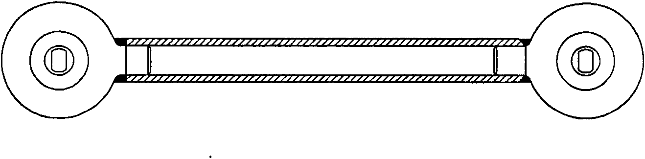
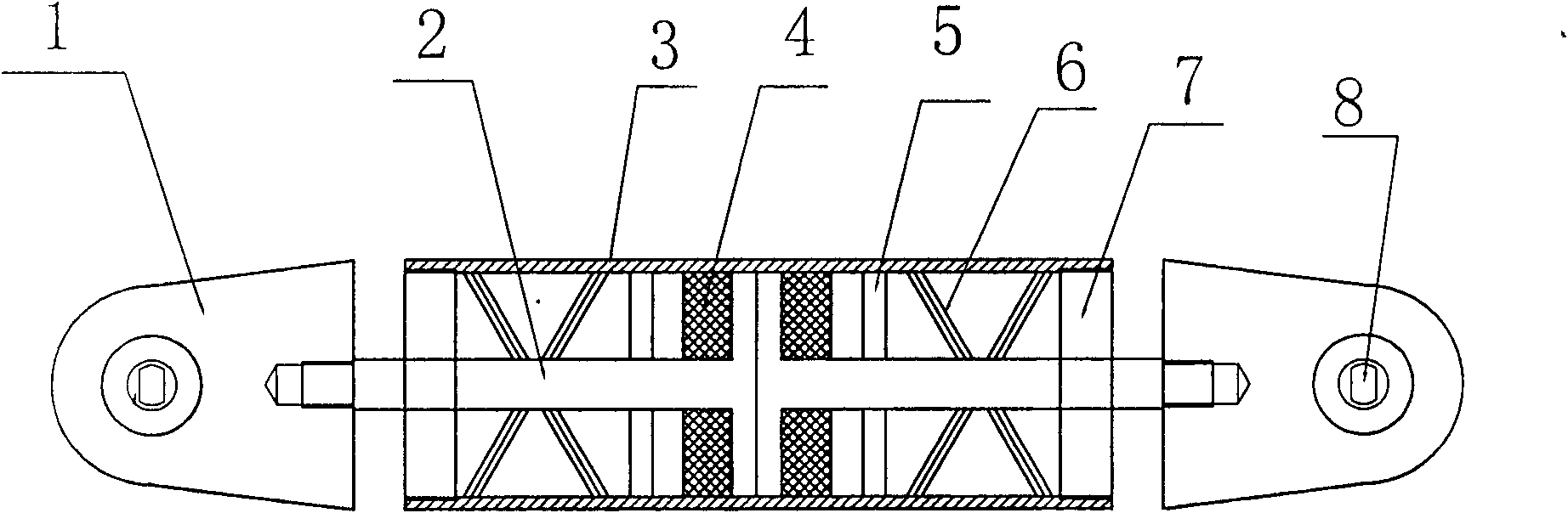
[0013] Thrust rod assembly of the present invention such as figure 2 shown.

[0014] The pull rod 2 is plunger-shaped and set back in the pull tube 3, from the root of the pull rod 2 plunger to the two ports of the pull tube 3, a rubber body 4, a retaining ring 5, a spring 6 and a blocking cover 7 are arranged in sequence.

[0015] The club head 1 is provided with a composite bearing 7 .

[0016] In actual work, because the metal bearing works with the rubber body and the spring at the same time, and interacts during work. The metal spring can adjust the displacement stroke and protect the rubber spring from excessive impulse value under a certain force value.

[0017] Due to the characteristics of this structure, no matter how much load the thrust rod is subjected to, the force of the rubber body is the overall force, and the force is very uniform, so the compressive strength of the rubber is greatly improved, so the risk of rubber rupture will be reduced. Reduced, thereb...


PUM


Abstract

The invention discloses a thrust rod assembly, comprising a rod head, a pull rod and a pull pipe, wherein the pull rod is arranged in the pull pipe back to back like a plunger; a rubber body, a baffle ring, a spring and a plugging cap are orderly arranged from the plunger root of the pull rod to the two ports of the pull pipe; and the rod head is internally provided with a composite bearing. The thrust rod assembly successfully solves the easy fracture phenomenon of the rubber bearing and greatly improves the loading force of the thrust rod; by utilizing the shock absorption function of the rubber body and the spring in the pull rod, the service life of the thrust rod is prolonged; and the assorted application of the composite bearing ensures the stability and the reliability of the thrust rod.

Description

technical field [0001] The invention relates to parts in the automobile balance bridge system, in particular to a thrust rod assembly. Background technique [0002] In the balanced positioning of double axles of medium and heavy trucks, the thrust rod assembly plays the role of positioning buffer. The current thrust rod assembly is as figure 1 As shown: it uses a pull rod in the middle, and the middle part of the rod head at both ends of the pull rod is a rubber bearing. [0003] With the above scheme, the rubber bearings on the rod heads at both ends are prone to rupture of the rubber body. The reason is that the displacement of the rubber body in the rod head is relatively small and the load is too large (>400000 at the maximum) when it is subjected to an instantaneous impact force. Niu), the rubber material of the rubber body is too small, and the force is uneven (the force volume accounts for about 30%), which causes the life of the thrust rod to be greatly reduced,...

Claims


Application Information

Patent Timeline
IPC IPC(8): B60G7/00
Inventor 王庆江
Owner 十堰市润莱机电制造有限公司
Why Eureka
Try Eureka