
Clamping and returning bending mechanism on automatic hoop bending machine for steel bars

A technology of bending mechanism and clamping mechanism, applied in the field of clamping and returning bending mechanism, can solve the problems of inability to bend quickly, not fully meet the needs of production, and inability to bend steel bars, and achieve flexible action, simple structure and strong adaptability. Effect

Inactive Publication Date: 2011-04-13
TJK MACHINERY TIANJIN
View PDF5 Cites 17 Cited by
  • Summary
  • Abstract
  • Description
  • Claims
  • Application Information

AI Technical Summary

Problems solved by technology

[0004] The above-mentioned prior art steel bar automatic hoop bending machine has the following defects: the prior art steel bar automatic hoop bending machine can only bend the steel bar input to the bending mechanism, that is, it can bend different parts of a steel bar, or bend the steel bar into various parts. Various shapes, such as triangle, square, circle, etc., but the other end of the steel bar cut by the shearing mechanism cannot be bent, that is, the long stirrup products with hooks at both ends cannot be quickly bent
Some products cannot be automatically completed on the equipment at one time, and cannot fully meet the needs of production

Method used


Image

  • Clamping and returning bending mechanism on automatic hoop bending machine for steel bars
  • Clamping and returning bending mechanism on automatic hoop bending machine for steel bars
  • Clamping and returning bending mechanism on automatic hoop bending machine for steel bars

Examples


Embodiment Construction

[0019] Embodiments of the present invention will be further described below in conjunction with the accompanying drawings.

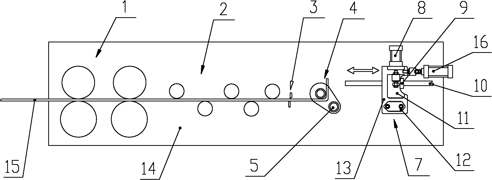
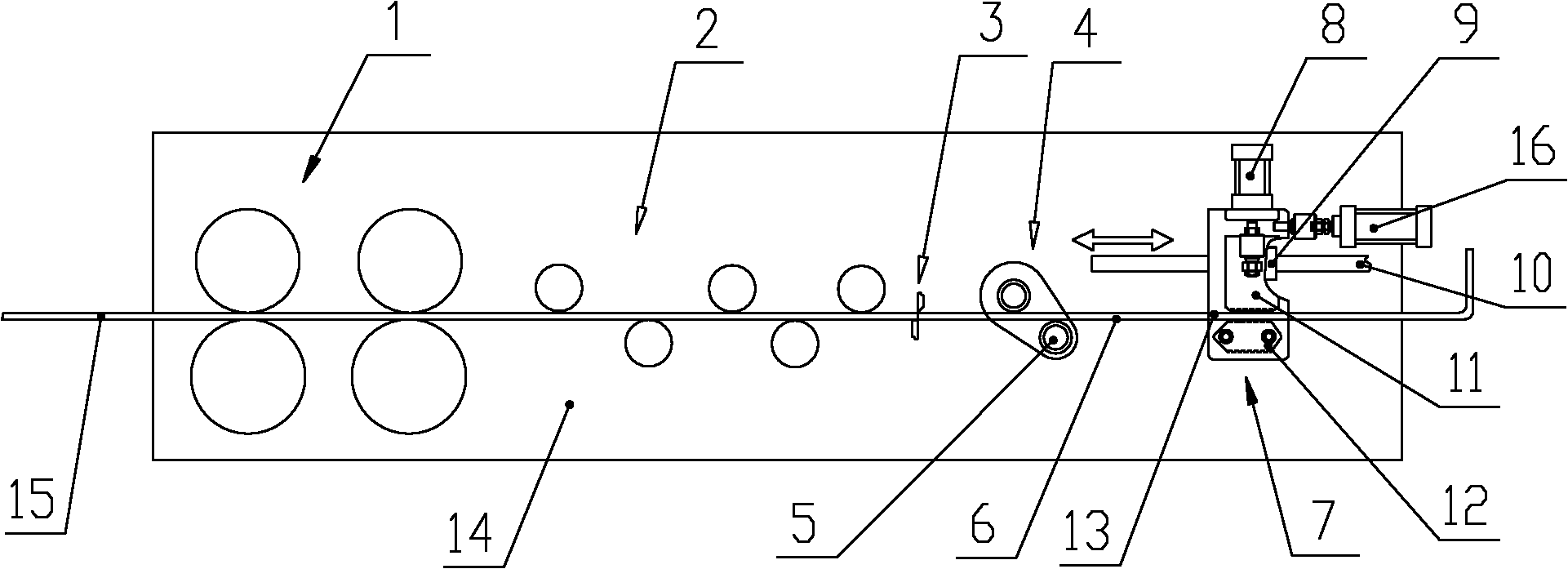
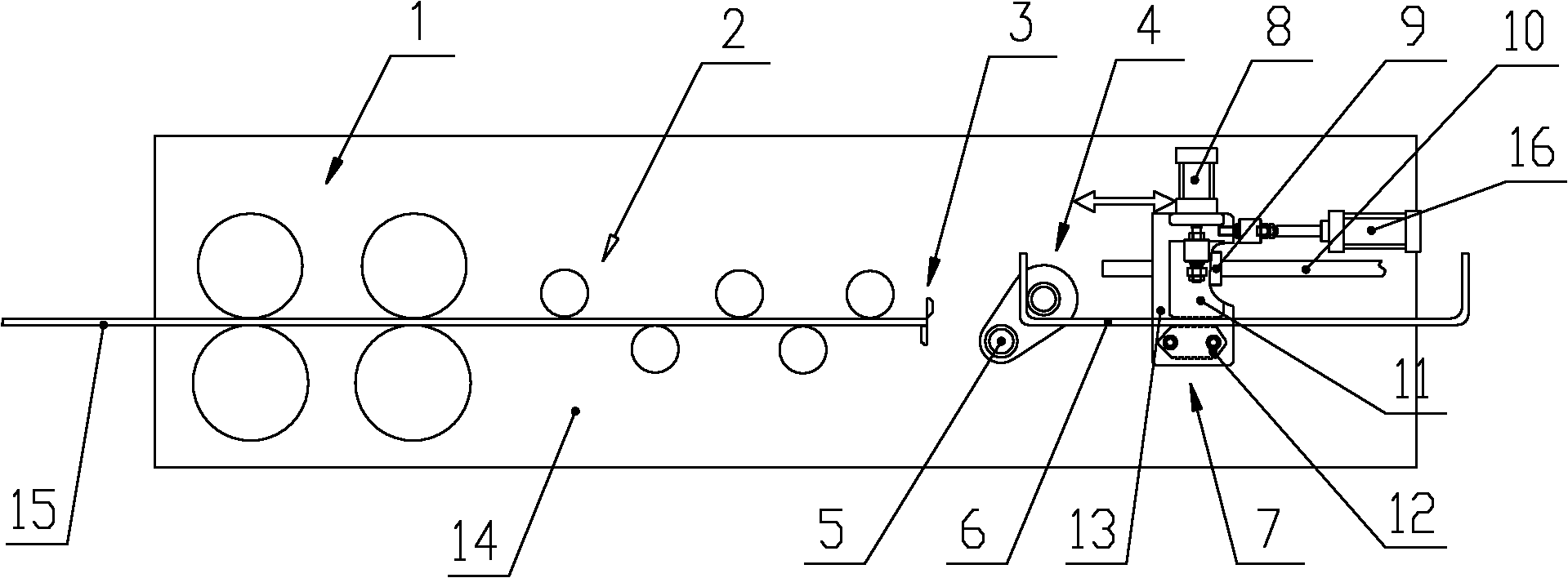
[0020] figure 1 It is a schematic diagram of the connection structure arranged on the automatic hoop bending machine of the present invention and a schematic diagram of the bending mechanism of the bending mechanism located on one side of the present invention: figure 2 yes figure 1 After the middle steel bar is bent by the bending mechanism, the movable clamping block of the present invention moves up, and after the steel bar continues to move forward, it is clamped by the clamping mechanism of the present invention to return the steel bar, and the shearing mechanism cuts off the steel bar schematic diagram: image 3 yes figure 2 In the present invention, after the steel bar is clamped, the steel bar is moved back, and the other end of the steel bar is bent by the bending mechanism; Figure 4 yes image 3 top view of Figure 5 yes image 3 Enlar...


PUM


Abstract

The invention discloses a clamping and returning bending mechanism on an automatic hoop bending machine for steel bars. The clamping and returning bending mechanism is positioned on one side of a bending mechanism on the automatic hoop bending machine for the steel bars, and comprises a guide rail and a clamping base plate, wherein the bottom of the guide rail is fixed on a frame; one side surface of the clamping base plate is arranged on the upper part of the guide rail in a sliding fit mode; a steel bar clamping mechanism is arranged on the other side surface of the clamping base plate; and the clamping base plate is connected with a reciprocation driving unit driving the clamping base plate to move. The invention has the advantages that: the other end of a steel bar sheared by a shearing mechanism is bent, namely products that two ends of the steel bar have the same shape can be rapidly bent at one time simultaneously, and the production requirement is met; the bending mechanism is simple in structure, low in cost and high in adaptability and can be matched with the automatic hoop bending machine for the steel bars and other equipment with a bending mechanism; the function of the hoop bending machine is expanded, so that a lot of hooping products can be machined by the clamping and returning bending mechanism; and the bending mechanism can bend coiled steel bars and also can rapidly bend straight steel bar-molded hooping products general for engineering.

Description

technical field [0001] The invention relates to an automatic hoop bending machine for steel bars, in particular to a clamping and returning bending mechanism on the automatic hoop bending machine for steel bars. Background technique [0002] With the rapid development of economic construction, the automatic processing equipment for stirrups - the automatic bending machine for steel bars has been widely used. The prior art steel bar automatic hoop bending machine comprises: a traction mechanism, a straightening mechanism, a bending mechanism and a shearing mechanism. [0003] The production process of the above-mentioned prior art steel bar automatic hoop bending machine is: after the steel bar passes through the traction mechanism, the straightening mechanism, and the bending mechanism, the steel bar is processed and bent into a stirrup of a certain shape, and then cut off by the shearing mechanism. [0004] The above-mentioned prior art steel bar automatic bending hoop mac...

Claims


Application Information

Patent Timeline
IPC IPC(8): B21F1/00
Inventor 陈振东
Owner TJK MACHINERY TIANJIN
Learn More