
Switch and method for manufacturing the same

A switch and substrate technology, applied in the direction of electrical switches, contacts, electrical components, etc., can solve the problems of complicated processing, rising cost, and complicated composition of movable contact springs, and achieve a simplified structure, simple manufacturing, and improved assembly workability. Effect

Active Publication Date: 2014-07-02
ORMON CORP
View PDF5 Cites 0 Cited by
  • Summary
  • Abstract
  • Description
  • Claims
  • Application Information

AI Technical Summary

Problems solved by technology

[0004] However, in the above-mentioned conventional switch, the structure of the movable contact spring is complicated, and the processing is complicated, and there is a problem that the cost increases.

Method used


Image

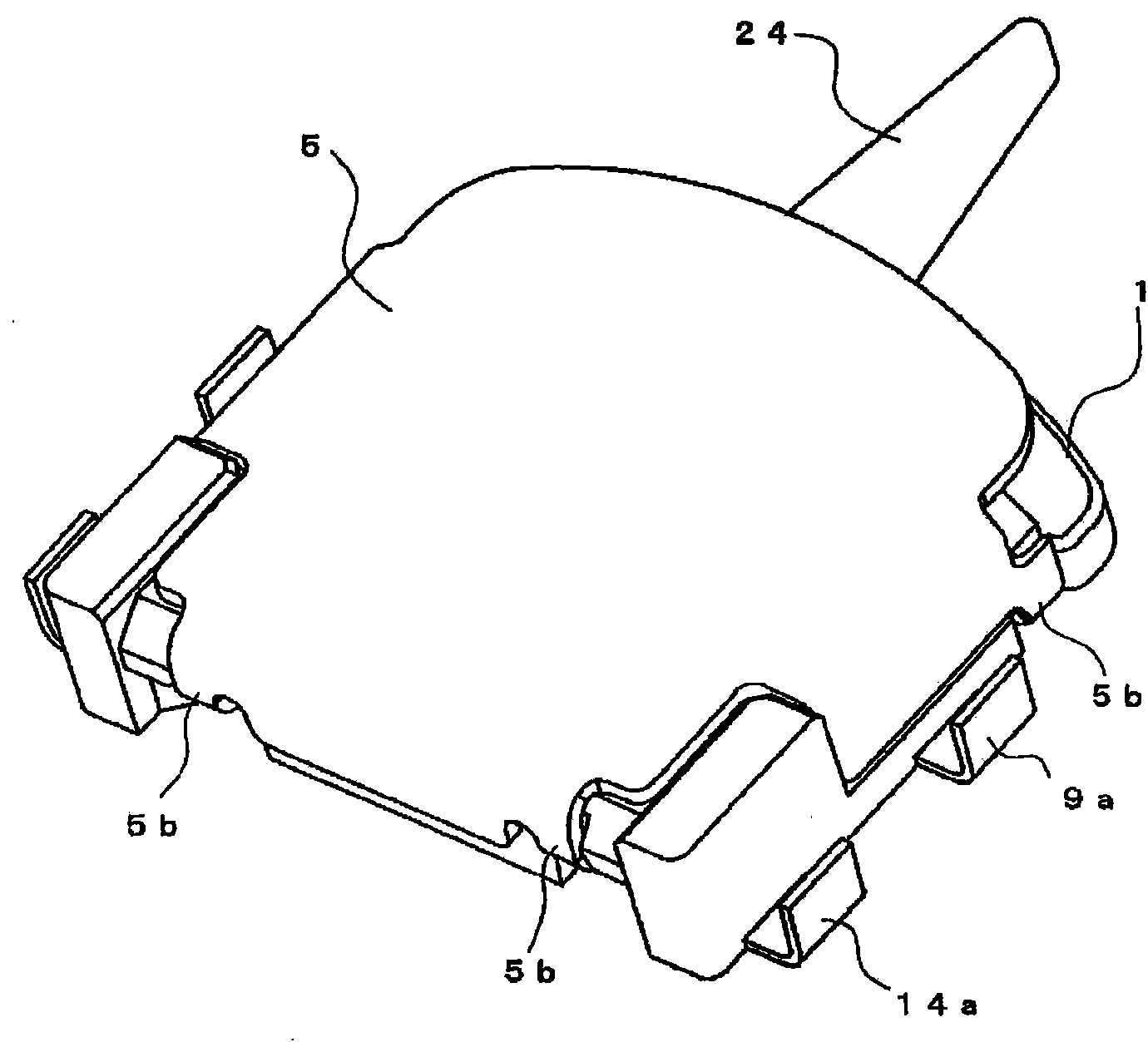
  • Switch and method for manufacturing the same
  • Switch and method for manufacturing the same
  • Switch and method for manufacturing the same

Examples


other Embodiment approach

[0164] The present invention is not limited to the configurations described in the above-mentioned embodiments, and various changes can be made.

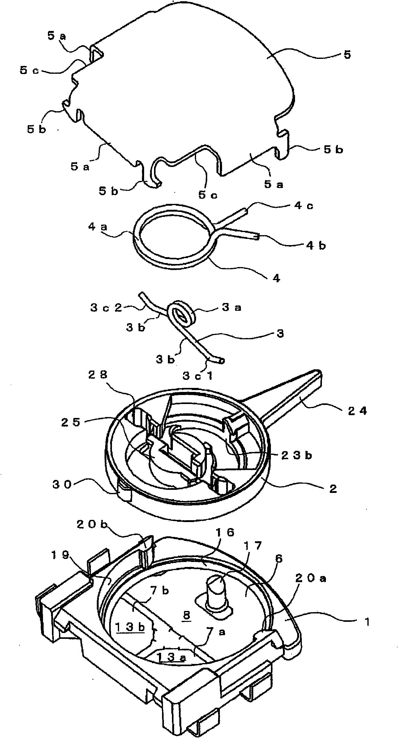
[0165] For example, in Figure 7 ~ Figure 9 Among them, the difference from the above-mentioned embodiment is the configuration of the movable contact spring 3 (the configuration of other parts is substantially the same).

[0166] That is, in the above-described embodiment, the position where the arm portions 3b, 3b at both ends protrude from the winding portion 3a is the lower side, that is, the base body 1 side. Figure 7 Among them, the difference is on the cover body 5 side.

[0167] In addition, in Figure 8 Among them, the elastic pressing portion is not constituted by the winding portion 3a, but is constituted by the bent portion 31 bent upward, that is, toward the side of the cover body 5, and the long hole 28 of the operation rod 2 for accommodating the movable contact spring 3 is formed straightly. different. According...


PUM


Abstract

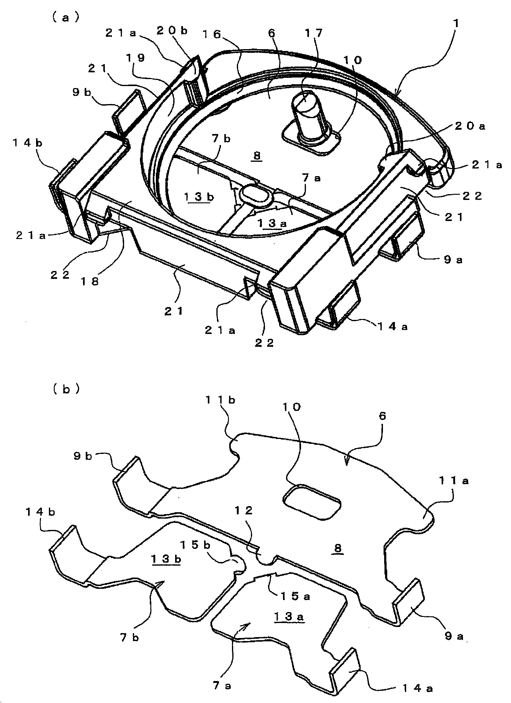
The present invention provides a switch that is simple in structure and can be produced cheaply. Therefore, this switch includes a base body (1) integrating a plurality of fixed terminals (6, 7a, 7b) and having fixed contact areas (8, 13a, 13b) for each fixed terminal (6, 7a, 7b). ); an operating lever (2), which is rotatably mounted on the base body (1) and is formed with a space (28) for exposing the exposed surface; a movable terminal (3), which is arranged on the operating lever (2) The space portion (28) rotates integrally and has a plurality of contact portions that are in sliding contact with the exposed surface of the base (1) and switch the conductive state with the fixed contact areas (8, 13a, 13b); The cover body (5) is installed on the base body (1) to prevent the operating rod (2) and the movable terminal (3) from falling off. The movable terminal (3) is provided with an elastic pressing part (3a). By mounting the cover (5) on the base (1), the elastic pressing part (3a) is pressed by the cover (5) to cause the contact part (3c) to move. ) can be crimped onto the fixed contact area (8, 13a or 13b).

Description

technical field [0001] The present invention relates to a switch, and more particularly to a switch for switching contacts by rotating operation and a method of manufacturing the same. Background technique [0002] Conventionally, as a switch, there is known a technique in which the rotating handle body is rotated by operating the operating body against the elastic force of the elastic body for reset, thereby switching the contactor through the movable contact spring mounted thereon. point (for example: refer to Patent Document 1). [0003] Patent Document 1: (Japanese) Unexamined Patent Publication No. 2004-362979 [0004] However, in the above-mentioned conventional switch, the structure of the movable contact spring is complicated, and the processing is complicated, and there is a problem that the cost increases. Contents of the invention [0005] Therefore, an object of the present invention is to provide a switch that has a simple structure and can be manufactured a...

Claims


Application Information

Patent Timeline
Patent Type & Authority Patents(China)
IPC IPC(8): H01H21/02H01H11/00H01H19/58H01H21/18
CPCH01H1/242H01H1/2041H01H1/365H01H21/24
Inventor 清野泰弘鸣尾俊博
Owner ORMON CORP
Learn More