


Quick Research
Generate reliable direction feasibility study reports for your R&D in just a few steps.

Technical Q&A
Discover and master advanced knowledge NOW. Basics, ideas, possibilities, all at once.

Find Solutions
As an expert in R&D theories, this can generate solutions to your technical problems instantly.

Evaluate Feasibility
Analyze your overall solution with one click, know your potential R&D risks in advance.

Monitor Landscape
Get weekly tech updates, stay abreast of the latest tech innovations and key insights.
Optical fiber junction terminating device
An optical fiber splicing and termination technology, applied in the direction of fiber mechanical structure, etc., can solve the problems of Oita, dedicated space for fiber distribution equipment, and the influence of terminal installation personnel on the termination of optical cables, and achieves the effect of saving transportation costs, manufacturing costs, and convenient use.
- Summary
- Abstract
- Description
- Claims
- Application Information
AI Technical Summary
Problems solved by technology
Method used
Image

Examples
Embodiment Construction
[0020] Specific embodiments of the present invention will be described in detail below in conjunction with the accompanying drawings.
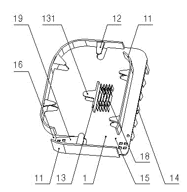
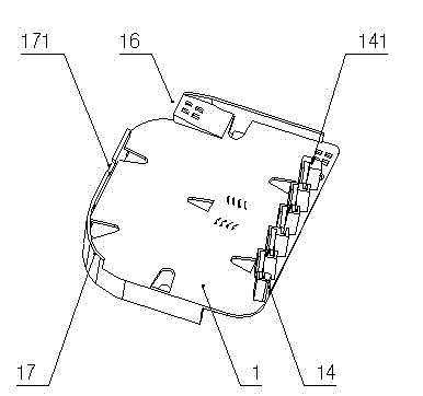
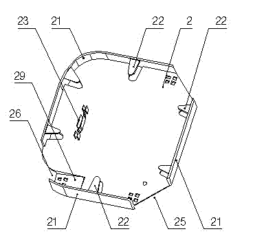
[0021] Such as figure 1 , figure 2 , Figure 5 , Image 6 As shown, an optical fiber splicing and terminating device according to the present invention includes: a wiring tray 3 and a splicing tray 1 that can be installed in an optical fiber splitting box—see Figure 8 As shown, the front of the fiber splicing tray 1 is provided with a splicing seat 18 and a ring of wire blocking boards 11, and the wire blocking board 11 is provided with a fiber inlet 15 and a fiber outlet 16, and the fiber splicing tray 1 is at the fiber outlet 16. A lead-out groove 19 transitioning from the front to the back is provided; an upper blocking piece 12 is provided on the inner wall of the wire blocking plate 11, a fiber card board 13 is provided on one side of the splicing seat 18, and a fiber card board 13 is provided on the outer wall There is an upper baf...
PUM
 Abstract
Description
Claims
Application Information
 - R&D Engineer
- R&D Manager
- IP Professional
- Industry Leading Data Capabilities
- Powerful AI technology
- Patent DNA Extraction
Browse by: Latest US Patents, China's latest patents, Technical Efficacy Thesaurus, Application Domain, Technology Topic, Popular Technical Reports.
© 2024 PatSnap. All rights reserved.Legal|Privacy policy|Modern Slavery Act Transparency Statement|Sitemap|About US| Contact US: help@patsnap.com