
Protective device for cleaning machine

A protection device and cleaning machine technology, applied in the field of cleaning machines, can solve the problems of high humidity of the protective cover environment, affecting the normal operation of the cleaning machine, endangering the personal safety of operators, etc., and achieving convenient and fast control and adjustment, convenient installation, and use. Life extension effect

Active Publication Date: 2011-04-06
TRUKING TECH LTD
View PDF4 Cites 3 Cited by
  • Summary
  • Abstract
  • Description
  • Claims
  • Application Information

AI Technical Summary

Problems solved by technology

However, when the screw rod drives the protective cover to rise, the electric wire passing through the screw rod will rise together, which brings inconvenience to the installation of the electric wire
Furthermore, when cleaning glass bottles, the environment in the protective cover has high humidity, and the motor in the protective cover is prone to safety failures, which will not only affect the normal operation of the cleaning machine, but also endanger the personal safety of the operator.

Method used


Image

  • Protective device for cleaning machine
  • Protective device for cleaning machine

Examples


Embodiment Construction

[0017] The present invention will be further described below in combination with specific embodiments and accompanying drawings.

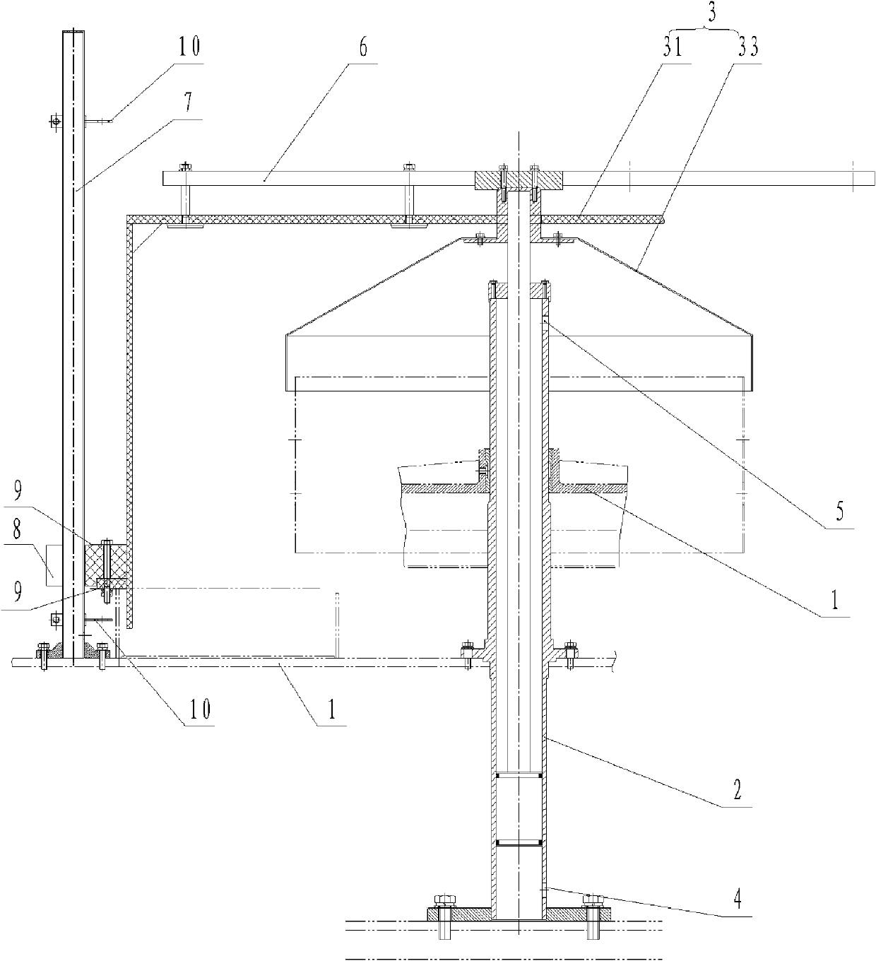
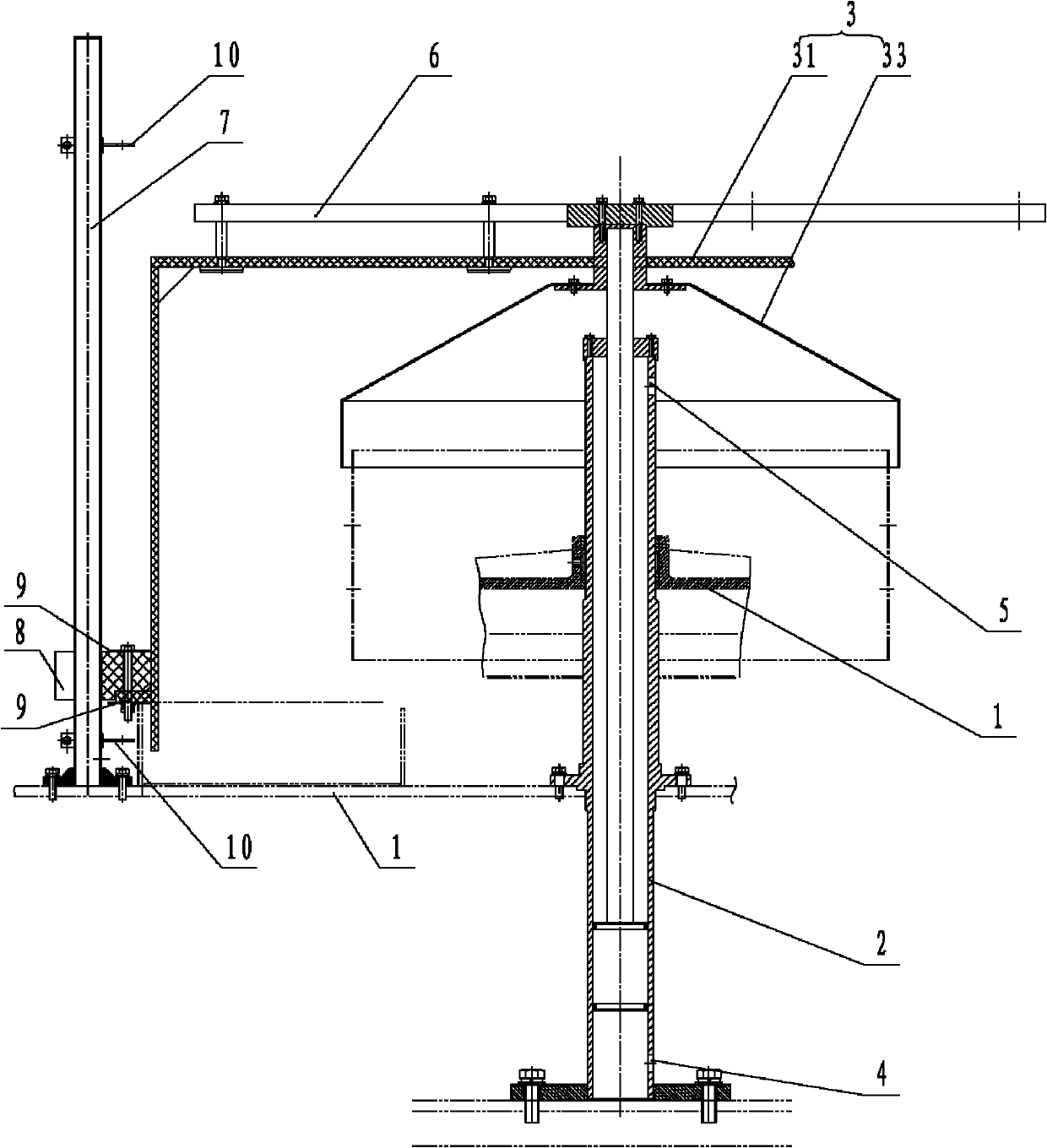
[0018] Such as figure 1 As shown, the protective device for washing machine of the present invention includes a frame 1 and a protective cover 3, the protective cover 3 is connected to the output end of a lifting drive cylinder, and the lifting drive cylinder is installed on the frame 1. The lifting drive cylinder is in the control mechanism (not shown in the figure) drives the protective cover 3 to lift under the control to realize the cover setting and opening of the cleaning machine. Its structure is simple and compact, and the cost is low. Control, its control and adjustment are convenient and quick. At the same time, the lifting drive cylinder is arranged at the rotation center of the protective cover 3, and the frame 1 can be centered through the outer wall of the lifting drive cylinder because it is directly sleeved on the outer wall of the...


PUM


Abstract

The invention discloses a protective device for a cleaning machine. The protective device comprises a stand and a protective cover, wherein the protective cover is connected with the output end of a lifting driving cylinder; and the lifting driving cylinder is arranged on the stand. The protective device for the cleaning machine of the invention has the advantages of simple and compact structure and low cost; the lifting speed of the protective cover is controlled by the extension speed of a piston rod of the driving cylinder, and conveniently and quickly controlled and adjusted; and the protective device is convenient to mount and works safely and reliably.

Description

technical field [0001] The invention relates to the field of pharmaceutical machinery and food packaging machinery, in particular to a washing machine. Background technique [0002] At present, in order to ensure the air cleanliness of the cleaning machine when cleaning glass bottles, it is generally necessary to cover the cleaning mechanism in the protective device. In the existing protective device, the protective cover is fixed on the screw rod, and the screw rod is driven up and down by the motor to realize the opening or covering of the protective cover. Due to the long stroke of the screw, in order to ensure the lifting stroke of the screw, the motor is connected to the middle and upper part of the screw through gears. When the protective cover is set on the cleaning mechanism, the motor will be in the protective cover. In order to avoid openings on the protective cover to penetrate the wires and affect the clean environment of the cleaning mechanism, one way is to op...

Claims


Application Information

Patent Timeline
Patent Type & Authority Applications(China)
IPC IPC(8): B08B13/00
Inventor 刘振邱永谋姜晓明唐岳
Owner TRUKING TECH LTD
Learn More