Method and device for detecting signals in multi-input and multi-output system
A detection signal and multi-output technology, applied in the field of communication, can solve problems such as low stability and high computational complexity, and achieve the effect of reducing computational complexity
- Summary
- Abstract
- Description
- Claims
- Application Information
AI Technical Summary
Problems solved by technology
Method used
Image
Examples
Embodiment 1
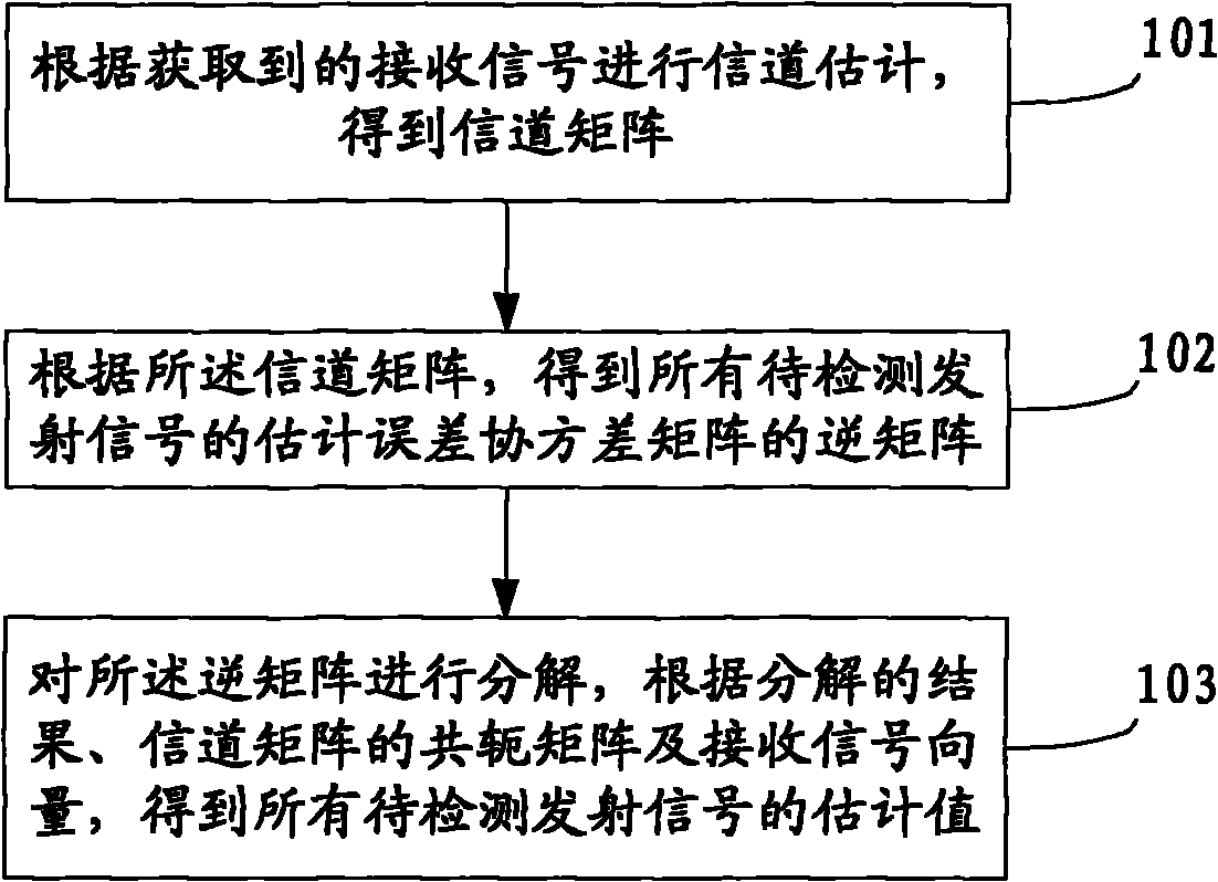
[0026] See figure 1 This embodiment provides a method for detecting signals in a multiple-input multiple-output system. The process of the method is as follows:
[0027] 101: Perform channel estimation according to the acquired received signal to obtain a channel matrix H;
[0028] 102: According to the channel matrix H, the inverse matrix R of the estimated error covariance matrix Q of all the transmitted signals to be detected is calculated;
[0029] 103: Decompose the inverse matrix R of the estimation error covariance matrix Q, and according to the result of the decomposition, the conjugate matrix H of the channel matrix H H And the received signal vector r to obtain the estimated values of all the transmitted signals to be detected.
[0030] This embodiment decomposes the inverse matrix R of the estimated error covariance matrix Q, and according to the result of the decomposition, the conjugate matrix H of the channel matrix H H And the received signal vector r, to obtain the e...
Embodiment 2
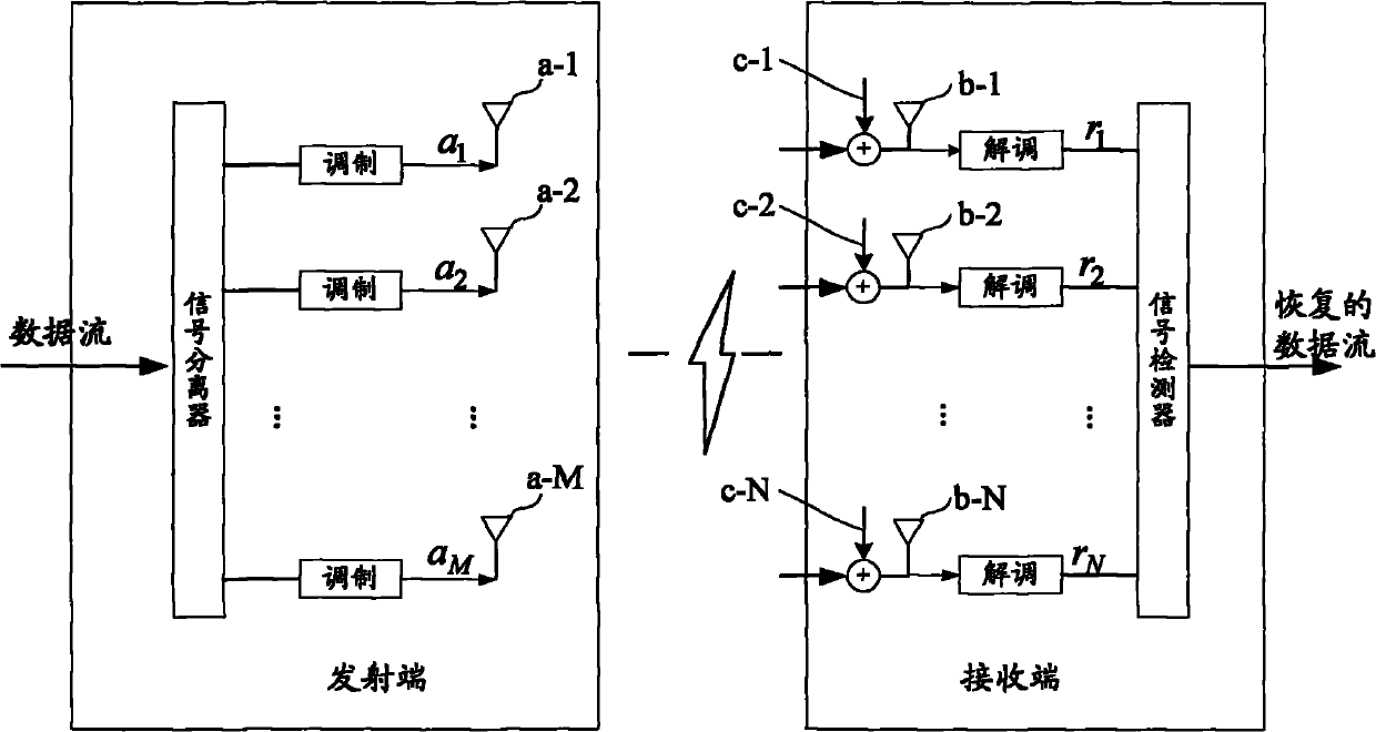
[0032] This embodiment provides a method for detecting signals in a multiple input multiple output system, such as figure 2 The shown multiple input multiple output system, transmitting signal a 1 ,..., a M They are respectively transmitted through M different transmitting antenna units a-1,..., a-M, and correspondingly, the received received signal r 1 ,..., r N They are received from N different receiving antenna units b-1,..., b-N. In this system, the number of transmitting antenna elements M is at least 2, and the number of receiving antenna elements N is at least M. Receive signal r 1 ,..., r N It is processed in the digital signal processor to produce the recovered transmit signal ..., figure 2 It also shows the summation components c-1, c-2,..., c-N, which represent the unavoidable noise signal w 1 , W 2 ,..., w N , These noise signals are respectively added to the received signals received by the receiving antenna units b-1, b-2,..., b-N.
[0033] The channel matrix H ...
Embodiment 3
[0059] This embodiment provides a method for detecting signals in a multiple-input multiple-output system. This embodiment takes an interference cancellation receiver for signal detection as an example. When an interference cancellation receiver is used for signal detection, the following steps are usually adopted:
[0060] a) Select one transmission signal each time as the current transmission signal to be detected, and use the linear minimum mean square error receiver to detect, and obtain the detection result of the current transmission signal to be detected;
[0061] b) Use the detection result of the current transmission signal to be detected to eliminate the interference of the current transmission signal to be detected on subsequent detections, and obtain the detection result of the next transmission signal to be detected;
[0062] c) Iterate steps a and b several times until all the transmitted signals are detected.
[0063] Specifically, for the detection result of the current...
PUM
 Abstract
Description
Claims
Application Information
 - R&D
- Intellectual Property
- Life Sciences
- Materials
- Tech Scout
- Unparalleled Data Quality
- Higher Quality Content
- 60% Fewer Hallucinations
Browse by: Latest US Patents, China's latest patents, Technical Efficacy Thesaurus, Application Domain, Technology Topic, Popular Technical Reports.
© 2025 PatSnap. All rights reserved.Legal|Privacy policy|Modern Slavery Act Transparency Statement|Sitemap|About US| Contact US: help@patsnap.com


