Method for testing cost of optical channel

A technology of optical channel cost and optical reception, which is applied in the field of optical communication, can solve the problems of increasing equipment and increasing production cost, and achieve the effect of less equipment, reducing production cost and improving efficiency

Inactive Publication Date: 2011-03-30
SUPERXON (CHENGDU) TECH LTD
View PDF1 Cites 7 Cited by
  • Summary
  • Abstract
  • Description
  • Claims
  • Application Information

AI Technical Summary

Problems solved by technology

However, the instruments used in the test system have increased accordingly, and the production cost has increased

Method used


Image

  • Method for testing cost of optical channel
  • Method for testing cost of optical channel
  • Method for testing cost of optical channel

Examples


Embodiment Construction

[0021] The technical solutions of the present invention will be further described below in conjunction with the accompanying drawings and through specific implementation methods.

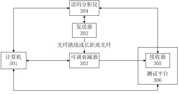
[0022] image 3 It is a system schematic diagram of testing optical channel cost of the present invention, and computer 301 is connected with adjustable attenuator 303, error code analyzer 304, test platform 306; Error code analyzer 304 is connected with transmitter 302 and receiver 305; The adjustable attenuator 302 is connected to the adjustable attenuator 303 to input optical power, the adjustable attenuator 303 is connected to the receiver 305, and the corresponding optical power is output to the receiver 305; the receiver 305 is placed on the test platform 306, and the computer 301 passes the test platform 306 reads back the current received optical power of the receiver.

[0023] Figure 4 It is a flow chart of the method for testing optical channel cost in the present invention. This schem...


PUM


Abstract

The invention discloses a method for testing the cost of an optical channel, which is suitable for a product calibrated by a receiver. Compared with a method for testing the cost of the optical channel by measuring sensitivity twice on the basis of an optical attenuator, the method for testing the cost of the optical channel solves the problems of plugging consistency of optical fibers, calibration of the variable optical attenuator and the like. Compared with a method for testing the cost of the optical channel by utilizing an optical switch, the method for testing the cost of the optical channel does not need to use an optical splitter or the optical switch. The method can reduce the cost of a test system and can also improve the accuracy of testing the cost of the optical channel.

Description

technical field [0001] The invention relates to the technical field of optical communication, in particular to a method for testing optical channel cost. Background technique [0002] The optical channel penalty is a significant drop in receiver sensitivity due to the distortion of the signal waveform during channel transmission. It manifests itself as a shift of the system's BER (Bit Error Rate) curve towards higher input power levels. This corresponds to a positive channel cost. In some cases there will be a negative channel cost, but the probability is small. (A negative channel penalty indicates that channel-dependent distortion actually improves the less-than-perfect transmitter eye.) Ideally, the BER curve would simply be shifted, but changes in shape are not uncommon and would indicate BER floor rise. Because the channel penalty varies with receiver sensitivity, it should be tested at a BER of 10-12. [0003] The need to test the channel penalty is because the to...

Claims


Application Information

Patent Timeline
Patent Type & Authority Applications(China)
IPC IPC(8): H04B10/08H04B10/071H04B10/079
Inventor 胥嫏
Owner SUPERXON (CHENGDU) TECH LTD
Why Eureka
Try Eureka