
Refueling machine

A fuel dispenser and oil gun technology, applied in special distribution devices, packaging, distribution devices, etc., can solve the problems of easy mopping, reduced service life, easy gun jamming, etc., to solve the problem of oil pipe mopping the floor, prolong the service life, and facilitate The effect of raising the gun

Active Publication Date: 2011-03-30
JIANGYIN FUREN HIGH TECH
View PDF4 Cites 6 Cited by
  • Summary
  • Abstract
  • Description
  • Claims
  • Application Information

AI Technical Summary

Problems solved by technology

[0003] 1. The tower box is a rectangular structure, and the oil guns are installed on the front and rear sides of the tower box in turn. For the eight-gun type tanker, four oil guns need to be placed side by side on the front and back sides of the tower box, and the horizontal length of the tower box is longer. , not applicable to places where the length of the gas station is limited
[0004] 2. The motor in the hydraulic cabinet is arranged on the side of the oil pump, and multiple sets of motors and oil pumps are arranged in sequence, which also makes the horizontal length of the hydraulic cabinet too wide, so that the overall length of the eight-gun type tanker is too long
[0005] 3. The oil gun cover is directly embedded in the tower box, making it difficult to carry the gun and easy to jam the gun
[0006] 4. It is difficult to adjust the tightness of the transmission belt of the motor and the oil pump. It basically depends on adjusting the center distance of the pulley to adjust the tightness of the belt. This is difficult to operate, and the adjustment is often not in place, resulting in a greatly shortened service life of the belt.
[0007] 5. Different numbers of guns can only be realized on different models
[0008] 6. The control box has single performance and poor versatility. A single model corresponds to a single control box, and there is no replaceability
[0009] 7. Due to the limitation of the height of the tanker and the oil outlet, the length of the oil pipe is limited. If it is too long, the oil pipe will drag the floor, greatly reducing the service life and affecting the appearance
[0010] 8. The oil outlet pipe adopts the connection method of high hanging and high hanging or low hanging and low hanging. The disadvantage of the high hanging and high hanging connection method is that it is inconvenient to inspect and operate; the disadvantage of the low hanging and low hanging connection method is that it is easy to mop the floor

Method used


Image

  • Refueling machine
  • Refueling machine
  • Refueling machine

Examples


Embodiment Construction

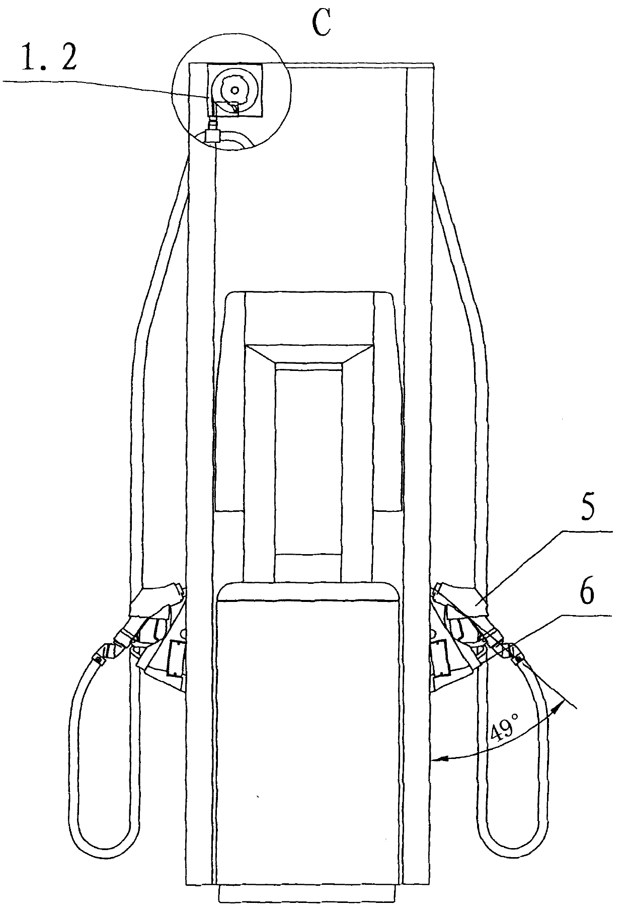
[0040] see Figure 1-Figure 3 , a kind of oil dispenser that the present invention relates to, it is mainly made up of tower box 1, hydraulic oil tank 2, control box 3, oil pipe 4, oil gun 5, oil gun cover 6, motor 7, oil pump 8 and belt 9;

[0041] The side of the tower box 1 is connected to the hydraulic oil tank 2, and the two form an "L"-shaped structure, and the control box 3 is arranged above the hydraulic oil tank 2 .

[0042] The front and rear sides of the tower box 1 are curved or polygonal, and the curved or polygonal surfaces are provided with a plurality of oil gun cover panels 11, and each of the oil gun cover panels 11 is provided with an oil gun cover panel 11. Gun cover 6, the oil gun cover 6 is provided with an oil gun 5, the oil gun 5 is connected to the output end of the oil pump 8 through the oil pipe 4, and the power end of the oil pump 8 is connected to the output end of the motor 7 through a belt 9; Said belt 9 is provided with tensioner 10, which is c...


PUM


Abstract

The invention relates to a refueling machine, which comprises a tower case (1), a hydraulic fuel tank (2) and a control box (3). The refueling machine is characterized in that: the lateral surface of the tower case (1) is connected with the hydraulic fuel tank (2) to form an L-shaped structure; the control box (3) is arranged above the hydraulic fuel tank (2); the front and rear surfaces of the tower case (1) are cambered or polygonal surfaces; a plurality of fuel gun cover panels (11) are arranged on the cambered or polygonal surfaces; a fuel gun cover (6) is arranged on each fuel gun cover panel (1); a fuel gun (5) is arranged on the fuel gun cover (6), and is connected with the output end of a fuel pump (8) through a fuel pipe (4); the power end of the fuel pump (8) is connected with the output end of a motor (7) through a belt (9); and the fuel pump (8), the belt (9) and the motor (7) are arranged in the hydraulic fuel tank (2). The refueling machine has a compact structure, a small volume and a modular design; the number of the oil guns can be set according to different needs; and the refueling machine is convenient to use and has wide application.

Description

technical field [0001] The invention relates to a device for refueling, liquid filling and dispensing. It specifically relates to a fuel dispenser. Background technique [0002] The fuel dispenser is a liquid volume measurement system for adding fuel to motor vehicles, and it is a fuel dispensing device commonly used in various gas stations. It includes a hydraulic cabinet, a tower box and a control box. The hydraulic cabinet is equipped with a motor and an oil pump, and the tower box is equipped with an oil gun. When working, the motor drives the oil pump to pump the fuel in the oil storage tank into the oil-gas separator through the oil pipe and filter for oil-gas separation, and then pumps down the fuel to the motor vehicle through the flow measurement converter and oil gun. It is divided into four-gun models, six-gun models, and eight-gun models. The main disadvantages of existing fuel dispensers are: [0003] 1. The tower box has a rectangular structure, and the oil...

Claims


Application Information

Patent Timeline
Patent Type & Authority Applications(China)
IPC IPC(8): B67D7/04B67D7/42B67D7/78
Inventor 张宇袁仁伟袁君伟邹龙飞吴文庆张先进胡逸徐东成夏新霞
Owner JIANGYIN FUREN HIGH TECH
Learn More