


Quick Research
Generate reliable direction feasibility study reports for your R&D in just a few steps.

Technical Q&A
Discover and master advanced knowledge NOW. Basics, ideas, possibilities, all at once.

Find Solutions
As an expert in R&D theories, this can generate solutions to your technical problems instantly.

Evaluate Feasibility
Analyze your overall solution with one click, know your potential R&D risks in advance.

Monitor Landscape
Get weekly tech updates, stay abreast of the latest tech innovations and key insights.
Logic control method and device of electric locomotive
A technology of electric locomotive and logic control, which is applied in the direction of electric program control, program control in sequence/logic controller, etc., and can solve the problem of low reliability
- Summary
- Abstract
- Description
- Claims
- Application Information
AI Technical Summary
Problems solved by technology
Method used
Image

Examples
Embodiment 1
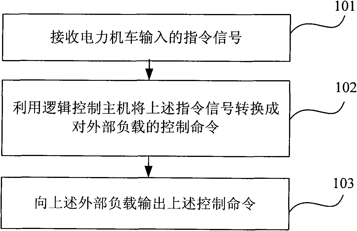
[0015] Such as figure 1 As shown, it is a flow chart of a logic control method for an electric locomotive according to an embodiment of the present invention. The method includes:
[0016] Step 101, receiving an instruction signal input by an electric locomotive.
[0017] Optionally, the above-mentioned instruction signal may be an instruction signal transmitted from the above-mentioned microcomputer control system of the electric locomotive. The above-mentioned command signal may be a 110V command signal transmitted from the above-mentioned electric locomotive driver controller / key switch group. The above command signal may be a 110V command signal transmitted from one or more of the main circuit breaker, isolating switch, two-position transfer switch, and auxiliary contact of the contactor of the electric locomotive.
[0018] Step 102, using the logic control host (where the logic control host is not necessarily a computer, but may be a logic control device such as a PC or...
Embodiment 2
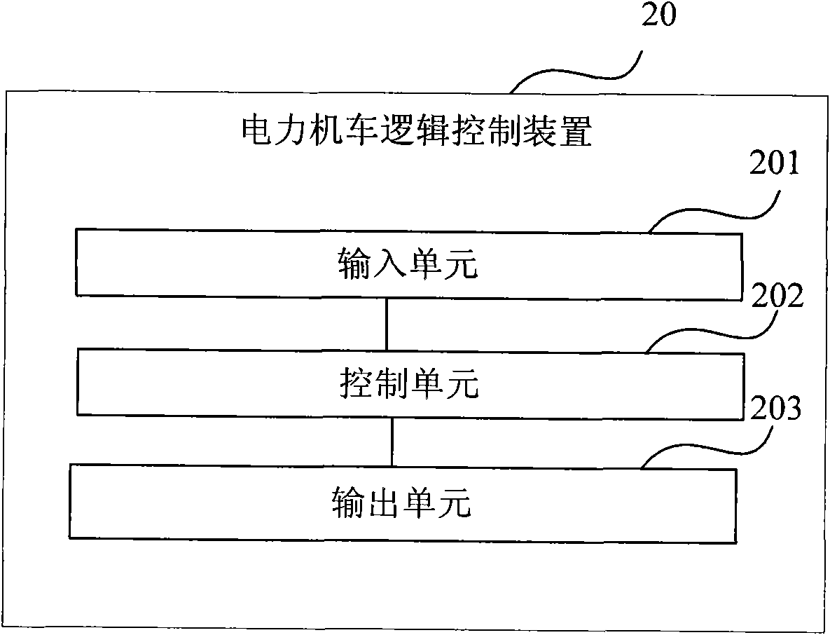
[0024] Such as figure 2 As shown, it is a schematic structural diagram of a logic control device for an electric locomotive according to an embodiment of the present invention. The above-mentioned device 20 includes: an input unit 201 for receiving command signals input by the electric locomotive; The logic control host is not necessarily a computer, but can be a logic control device such as a PC or a microprocessor) to convert the above-mentioned command signal into a control command for the external load; the output unit 203 is used to output the above-mentioned control command to the above-mentioned external load.
[0025] Optionally, the command signal received by the input unit 201 may be the command signal transmitted from the microcomputer control system of the electric locomotive. The command signal received by the input unit 201 may be a 110V command signal transmitted from the electric locomotive driver controller / key switch group. The command signal received by th...
Embodiment 3
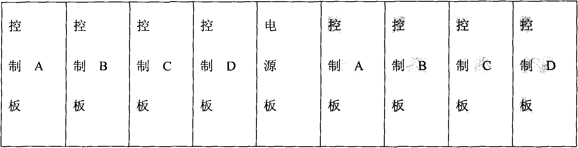
[0030] The above-mentioned electric locomotive logic control device can be an electric locomotive logic control unit (LCU), which is equivalent to a common programmable logic controller (PLC). function), output unit (realize the function of the above output unit) and peripheral connector (realize the function of the above input unit), this device can be installed in a suitable position inside the locomotive, and a large number of external connections can be reduced by using this device And the use of relays, and the input and output status of each link of the locomotive control circuit can be observed at any time through the status light display unit, which brings great convenience to the safe operation and maintenance of the locomotive. The logic control unit of the electric locomotive is installed in an appropriate position in the locomotive equipment room, and the locomotive provides a DC 110V working power supply, and the input and output signals of the locomotive are excha...
PUM
 Abstract
Description
Claims
Application Information
 - R&D Engineer
- R&D Manager
- IP Professional
- Industry Leading Data Capabilities
- Powerful AI technology
- Patent DNA Extraction
Browse by: Latest US Patents, China's latest patents, Technical Efficacy Thesaurus, Application Domain, Technology Topic, Popular Technical Reports.
© 2024 PatSnap. All rights reserved.Legal|Privacy policy|Modern Slavery Act Transparency Statement|Sitemap|About US| Contact US: help@patsnap.com